Hyundai Palisade (LX2): Rear Corner Radar System / Warning Indicator
Components and components location
| Components |
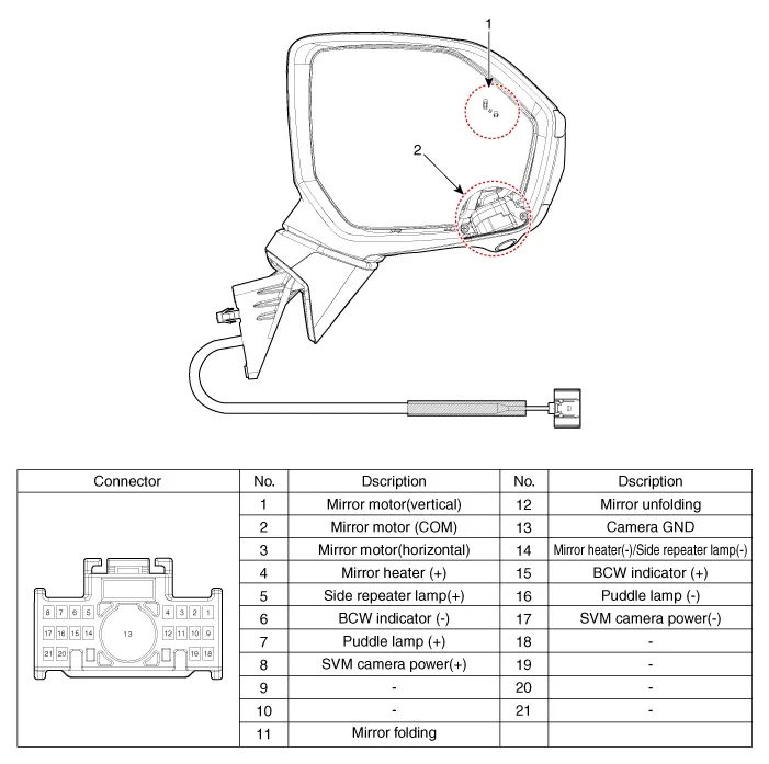
| 1. Warning indicator |
2. SVM camera |
Repair procedures
| Removal |
| 1. |
Disconnect the negative (-) battery terminal.
|
| 2. |
Remove the front door trim.
(Refer to Body - "Front door trim")
|
| 3. |
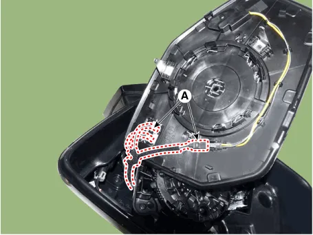
Remove the outside rear view cover (A).
|
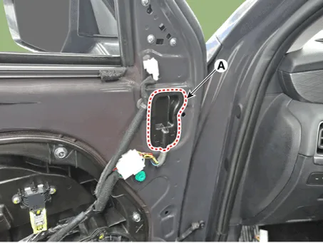
| 4. |
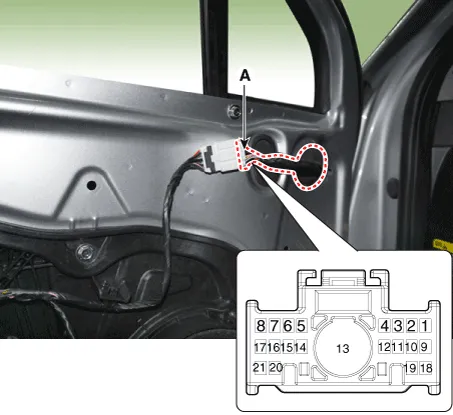
Disconnect the mirror connector (A).
|
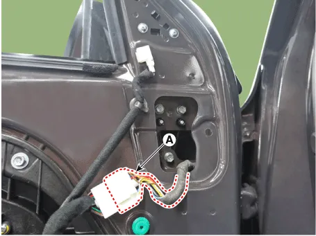
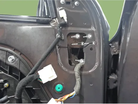
| 5. |
Loosen the mounting nut and then remove the outside rear view mirror.
|
| 6. |
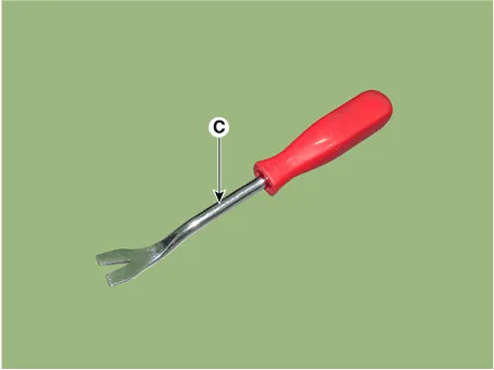
Using a fastener remover (C), remove the mirror (A) as illustration
below.
|


| 7. |
Disconnect heat wire connectors (A) and then remove the mirror.
|
| Installation |
| 1. |
Install the outside mirror.
|
| 2. |
Connect the negative (-) battery terminal.
|
| Inspection |
| 1. |
Disconnect the power door mirror connector from the harness
|
Components and components location Circuit Diagram Repair procedures Inspection 1. Disconnect the negative (-) battery terminal.
Other information:
Hyundai Palisade (LX2) 2020-2026 Service Manual: Immobilizer Control Unit
Repair procedures Removal 1. Disconnect the negative (-) battery terminal. 2. Remove the glove box housing. (Refer to Body - "Glove Box Housing Cover") 3.
Hyundai Palisade (LX2) 2020-2026 Service Manual: Temperature Control Actuator
Description and operation Description The heater unit includes mode control actuator and temperature control actuator. The temperature control actuator is located at the heater unit. It regulates the temperature by the procedure as follows.
Categories
- Manuals Home
- Hyundai Palisade Owners Manual
- Hyundai Palisade Service Manual
- Lift and Support Points
- Automatic Transaxle Fluid (ATF)
- Components and components location
- New on site
- Most important about car

Copyright © 2026 www.hpalisadelx.com - 0.0164