Hyundai Palisade (LX2): Engine Control System / Components and components location
| Components Location |

| 1. ECM
(Engine Control Module) 2. Intake Air Temperature Sensor (IATS) 3. Manifold Absolute Pressure Sensor (MAPS) 4. Engine Coolant Temperature Sensor (ECTS) 5. Throttle Position Sensor (TPS) [integrated into ETC Module] 6. Crankshaft Position Sensor (CKPS) 7. Camshaft Position Sensor (CMPS) [Bank 1 / Intake] 8. Camshaft Position Sensor (CMPS) [Bank 1 / Exhaust] 9. Camshaft Position Sensor (CMPS) [Bank 2 / Intake] 10. Camshaft Position Sensor (CMPS) [Bank 2 / Exhaust] 11. Knock Sensor (KS) [Bank 1] 12. Knock Sensor (KS) [Bank 2] 13. Heated Oxygen Sensor (HO2S) [Bank 1 / Sensor 1] 14. Heated Oxygen Sensor (HO2S) [Bank 1 / Sensor 2] 15. Heated Oxygen Sensor (HO2S) [Bank 2 / Sensor 1] 16. Heated Oxygen Sensor (HO2S) [Bank 2 / Sensor 2] 17. Rail Pressure Sensor (RPS) 18. CVVT Oil Temperature Sensor (OTS) |
19. CVVT
Oil Pressure Sensor (OPS) 20. Accelerator Position Sensor (APS) 21. A/C Pressure Transducer (APT) 22. ETC Motor (integrated info ETC module] 23. Injector 24. Purge control solenoid valve (PCSV) 25. Variable Force Solenoid (VFS) [Bank 1 / Intake] 26. CVVT Oil Control Valve (OCV) [Bank 1 / Exhaust] 27. Variable Force Solenoid (VFS) [Bank 2 / Intake] 28. CVVT Oil Control Valve (OCV) [Bank 2 / Exhaust] 29. Fuel Pressure Control Valve (FPCV) 30. Variable Intake Solenoid (VIS) valve #1 31. Variable Intake Solenoid (VIS) valve #2 32. Ignition Coil 33. Fuel Pump Relay 34. Data Link Connector (DLC) [16 pin] 35. Multi-Purpose Check Connector [20 pin 36. Main Relay |
|
1. ECM (Engine Control Module) |
2. Intake Air Temperature Sensor (IATS) 3. Manifold Absolute Pressure Sensor (MAPS) |
|
|
|
|
4. Engine Coolant Temperature Sensor (ECTS) |
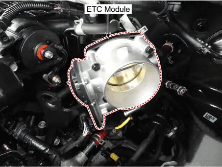
5. Throttle Position Sensor (TPS) [integrated into ETC Module] 22. ETC Motor (integrated info ETC Module) |
|
|
|
|
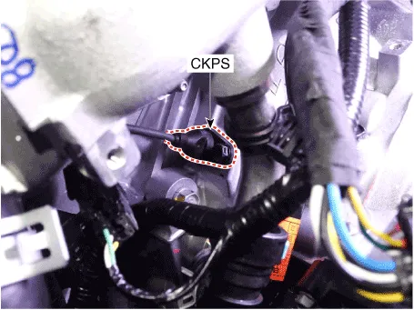
6. Crankshaft Position Sensor (CKPS) |
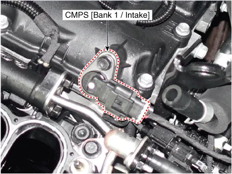
7. Camshaft Position Sensor (CMPS) [Bank 1 / Intake] |
|
|
|
|
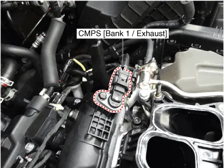
8. Camshaft Position Sensor (CMPS) [Bank 1 / Exhaust] |
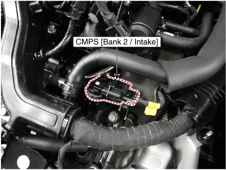
9. Camshaft Position Sensor (CMPS) [Bank 2 / Intake] |
|
|
|
|
10. Camshaft Position Sensor (CMPS) [Bank 2 / Exhaust] |
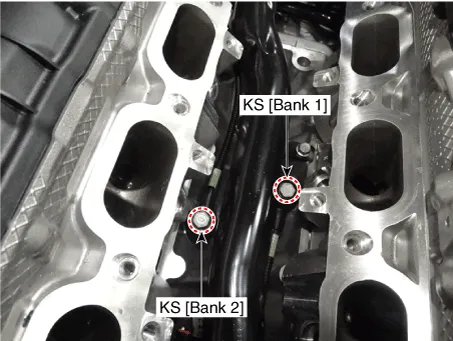
11. Knock Sensor (KS) [Bank 1] 12. Knock Sensor (KS) [Bank 2] |
|
|
|
|
13. Heated Oxygen Sensor (HO2S) [Bank 1 / Sensor 1] |
14. Heated Oxygen Sensor (HO2S) [Bank 1 / Sensor 2] |
|
|
|
|
15. Heated Oxygen Sensor (HO2S) [Bank 2 / Sensor 1] |
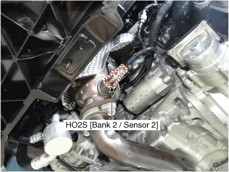
16. Heated Oxygen Sensor (HO2S) [Bank 2 / Sensor 2] |
|
|
|
|
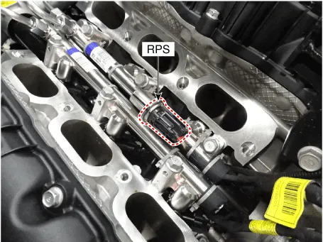
17. Rail Pressure Sensor (RPS) |
18. CVVT Oil Temperature Sensor (OTS) 19. CVVT Oil Pressure Sensor (OPS) |
|
|
|
|
20. Accelerator Position Sensor (APS) |
21. A/C Pressure Transducer (APT) |
|
|
|
|
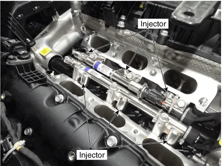
23. Injector |
24. Purge control solenoid valve (PCSV) |
|
|
|
|
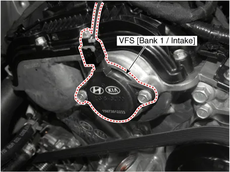
25. Variable Force Solenoid (VFS) [Bank 1 / Intake] |
26. CVVT Oil Control Valve (OCV) [Bank 1 / Exhaust] |
|
|
|
|
27. Variable Force Solenoid (VFS) [Bank 2 / Intake] |
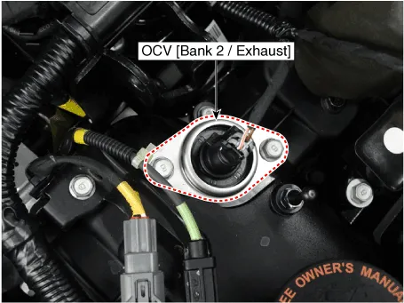
28. CVVT Oil Control Valve (OCV) [Bank 2 / Exhaust] |
|
|
|
|
29. Fuel Pressure Control Valve (FPCV) |
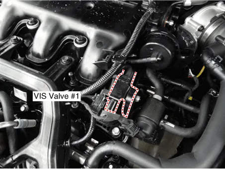
30. Variable Intake Solenoid (VIS) valve #1 |
|
|
|
|
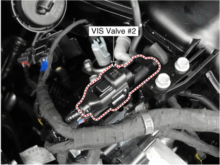
31. Variable Intake Solenoid (VIS) valve #2 |
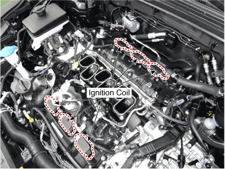
32. Ignition Coil |
|
|
|
|
36. Main Relay [EMS Box] 33. Fuel Pump Relay [EMS Box] |
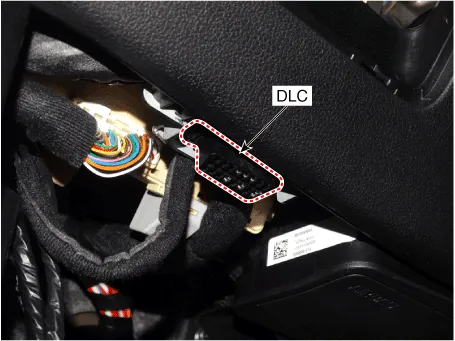
34. Data Link Connector (DLC) [16 pin] |
|
|
|
|
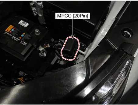
35. Multi-Purpose Check Connector [20 pin] |
|
|
|


Description If the Gasoline Engine Control system components (sensors, ECM, injector, etc.) fail, interruption to the fuel supply or failure to supply the proper amount of fuel for various engine operating conditions will result.
Other information:
Hyundai Palisade (LX2) 2020-2026 Service Manual: Blower Motor
Repair procedures Inspection 1. Connect the battery voltage and check the blower motor rotation. 2. If the blower motor does not operate well, substitute with a known-good blower motor and check for proper operation.
Hyundai Palisade (LX2) 2020-2026 Service Manual: Description and operation
Description • PDW consists of 8 sensors (front : 4 units, rear : 4 units) that are used to detect obstacles and transmit the result in three separate warning levels, the first, second and third to IBU via LIN communication.
Categories
- Manuals Home
- Hyundai Palisade Owners Manual
- Hyundai Palisade Service Manual
- General Tightening Torque Table
- Power Outlet
- Electronic Child Safety Lock System
- New on site
- Most important about car
