
Hyundai Palisade (LX2): Heater / Temperature Control Actuator
Description and operation
| Description |
Components and components location
| Component Location |
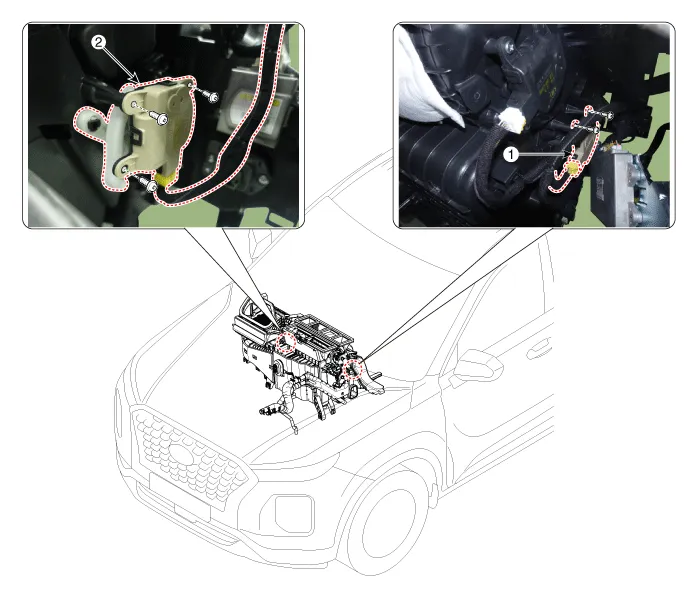
| 1. Temperature control actuator
[LH] |
2. Temperature control actuator
[RH] |
Repair procedures
| Inspection |
| 1. |
Turn the ignition switch OFF.
|
| 2. |
Disconnect the temperature control actuator connector.
|
| 3. |
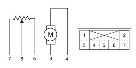
Verify that the temperature control actuator operates to the cool position
when connecting 12V to terminal 3 and grounding terminal 4.
Verify that the temperature control actuator operates to the warm position
when connected in reverse.
[Driver]
[Passenger]
|
| 4. |
Connect the temperature control actuator connector.
|
| 5. |
Turn the ignition switch ON.
|
| 6. |
Check the voltage between terminal 5 and 6.
Specification
It will feedback the current position of the actuator to controls.
|
| 7. |
If the measured voltage is not within specification, substitute with
a known-good temperature control actuator and check for proper operation.
|
| 8. |
Replace the temperature control actuator if it is proved that there
is a problem with it.
|
| Replacement |
| 1. |
Disconnect the negative (-) battery terminal.
|
| 2. |
Remove the crash pad lower panel.
(Refer to Body - "Crash Pad Lower Panel")
|
| 3. |
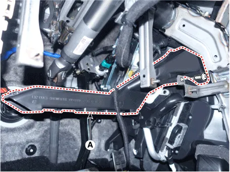
Loosen the mounting screws and remove the shower duct [LH] (A).
|
| 4. |
Separate the Surround view monitoring (SVM) unit.
(Refer to Body Electrical System - "SVM Unit")
|
| 5. |
Separate the temperature control actuator connector (A) and loosen the
mounting screw and remove the temperature control actuator (B).
|

| 6. |
Install in the reverse order of removal.
|
| 1. |
Disconnect the negative (-) battery terminal.
|
| 2. |
Remove the crash pad center panel.
(Refer to Body - "Crash Pad Center Panel")
|
| 3. |
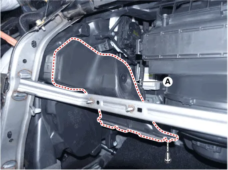
Loosen the mounting screws and remove the shower duct [RH] (A).
|
| 4. |
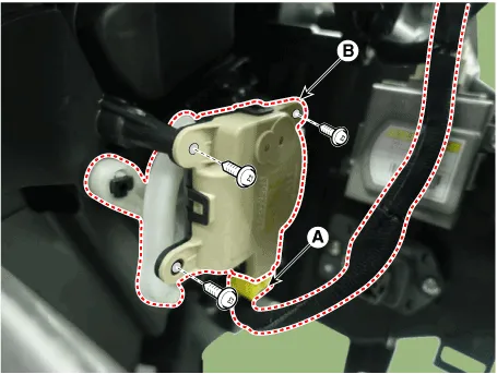
Separate the temperature control actuator connector (A) and loosen the
mounting screw and remove the temperature control actuator (B).
|
| 5. |
Install in the reverse order of removal.
|
Description and operation Description The PTC (Positive Temperature Coefficient) heater is installed at the exit or the backside of the heater core.
Description and operation Description The mode control actuator is located at the heater unit. It adjusts the position of the mode door by operating the mode control actuator based on the signal of the A/C control unit.
Other information:
Hyundai Palisade (LX2) 2020-2026 Service Manual: Schematic diagrams
System Block Diagram Component Parts And Function Outline Component part Function Vehicle-speed sensor, ESP/ABS Control Module Converts vehicle speed to pulse. ECM Receives signals from sensor and control switches.
Hyundai Palisade (LX2) 2020-2026 Service Manual: Description and operation
Description Rear view camera will activate when the backup light is ON with the ignition switch ON and the shift lever in the R position. This system is a supplemental system that shows behind the vehicle through the AV monitor or the ECM (Reverse Display Room Mirror) mirror while backing-up.
Categories
- Manuals Home
- Hyundai Palisade Owners Manual
- Hyundai Palisade Service Manual
- General Tightening Torque Table
- Engine Control/Fuel System
- Scheduled maintenance services
- New on site
- Most important about car
