Hyundai Palisade (LX2): Immobilizer System / Immobilizer Control Unit
Repair procedures
| Removal |
| 1. |
Disconnect the negative (-) battery terminal.
|
| 2. |
Remove the glove box housing.
(Refer to Body - "Glove Box Housing Cover")
|
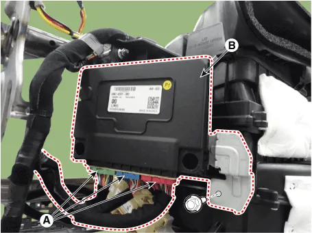
| 3. |
Disconnect the connector (A) and then remove the IBU (B) after loosening
mounting nuts.
|
| Installation |
| 1. |
Install the IBU after connecting the unit connector.
|
| 2. |
Install the glove box housing.
|
| 3. |
Connect the negative (-) battery terminal.
|
Diagnosis with Diagnostic tool 1. In the body electrical system, failure can be quickly diagnosed by using the vehicle diagnostic system (Diagnostic tool).
Repair procedures Removal 1. Disconnect the negative (-) battery terminal. 2. Remove the crash pad lower panel.
Other information:
Hyundai Palisade (LX2) 2020-2026 Service Manual: Repair procedures
Diagnosis with Diagnostic tool 1. In the body electrical system, failure can be quickly diagnosed by using the vehicle diagnostic system (Diagnostic tool). The diagnostic system (Diagnostic tool) provides the following information.
Hyundai Palisade (LX2) 2020-2026 Service Manual: Description and operation
Description The smart cruise control system allows a driver to program the vehicle to control the speed and following distance by detecting the vehicle ahead without depressing the brake pedal or the accelerator pedal. 1.
Categories
- Manuals Home
- Hyundai Palisade Owners Manual
- Hyundai Palisade Service Manual
- Resetting the Driver's Seat Memory System
- Power Outlet
- How to reset the power liftgate
- New on site
- Most important about car
