Hyundai Palisade (LX2): Parking Distance Warning (PDW) / Description and operation
Hyundai Palisade (LX2) 2020-2026 Service Manual / Advanced Driver Assistance System (ADAS) / Parking Distance Warning (PDW) / Description and operation
| Description |
| • |
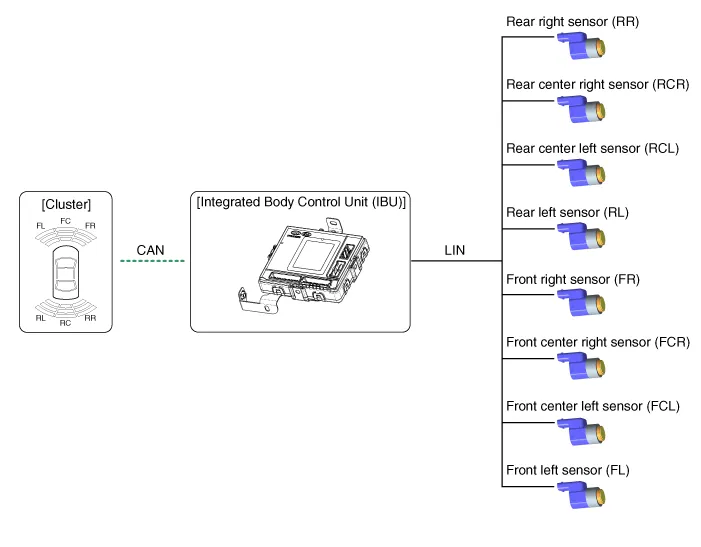
PDW consists of 8 sensors (front : 4 units, rear : 4 units) that are
used to detect obstacles and transmit the result in three separate warning
levels, the first, second and third to IBU via LIN communication.
|
| • |
IBU decides the alarm level by the transmitted communication message
from the slave sensors, then operates the buzzer or transmits the data
for display.
|
Block Diagram
System Operation Specification
| Initial mode |
| 1. |
System initializing time
|
| 2. |
PDW recognizes LID and sets the sensor ID up during initialization.
|
| 3. |
PDW activates each sensor and then executes the diagnosis after finishing
initialization of IPM(IBU).
|
| 4. |
PDW starting buzzer is normally worked, when sensor does not send an
error message and after finishing error diagnosis.
|
| 5. |
If any failure is received from the any sensors, PDW starting buzzer
does not work but the failure alarm is operated for a moment.
If you have display option, warning sign is also shown on it.
|

| 6. |
IBU memorizes the completed initializing status of sensor.
|
| Normal mode |
| 7. |
PDW-F : Lin communication starts and keeps the routine after IGN1 ON+D
gear + below 10 km/h.
PDW-R : Lin communication starts and keeps the routine after IGN1 ON+R
gear
|
| 8. |
After initializing, the routine starts at once without PDW starting
warning sound.
|
| 9. |
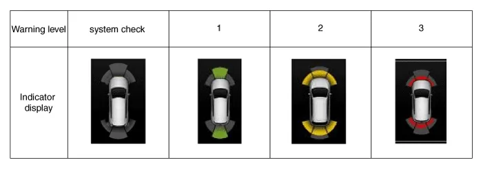
Alarms of obstacle consists of 3 level 1,2,3 step and 1,2 alarm sounds
intermittently and 3 alarm sounds continuously. 1 level alarm doesn't
exist in the front ultrasonic sensor.
|
| 10. |
In display, the data of each sensor is sent from IBU to display, for
example cluster. CAN communication is used for transmission and maximum
gateway time is 50ms.
|
| 11. |
The efficient vehicle speed of PDW operation is under 10Km/h.
|
| 12. |
Operation doesn't start or stops at gear N, P.
|
Sensing Area
|
Level |
Distance range |
Allowed range |
|
1 |
Front : 61 - 100 cm (24.02 - 39.37 in.) / Rear : 61 - 120 cm (24.02 - 47.2
in.) |
± 15 cm (5.90 in.) |
|
2 |
31 - 60 cm (12.20 - 23.62 in.) |
± 15 cm (5.90 in.) |
|
3 |
0 - 30 cm (0 - 11.81 in) |
± 10 cm (3.94 in.) |
*Measurement condition : PVC pipe - Diameter 75 mm (0.0394 in.), length 1 m
(39.37 in.), at normal temperature
Display Alarm Indicator Specification
Component Location 1. IBU (Integrated Body Control Unit) 2. Parking distance warning sensor ※ Parking Distance Warning function is built in IBU (Integrated Body Control Unit).
Schematic diagrams Schematic Diagrams Repair procedures Removal 1. Remove the bumper cover. (Refer to Body - "Front Bumper Cover") (Refer to Body - "Rear Bumper Cover") 2.
Other information:
Hyundai Palisade (LX2) 2020-2026 Service Manual: Components and components location
Hyundai Palisade (LX2) 2020-2026 Service Manual: Ultrasonic Sensor
Schematic diagrams Schematic Diagrams Repair procedures Removal 1. Remove the bumper cover. (Refer to Body - "Front Bumper Cover") (Refer to Body - "Rear Bumper Cover") 2.
Categories
- Manuals Home
- Hyundai Palisade Owners Manual
- Hyundai Palisade Service Manual
- Rear Heater Unit
- Lift and Support Points
- Resetting the Driver's Seat Memory System
- New on site
- Most important about car

Copyright © 2026 www.hpalisadelx.com - 0.0181