Hyundai Palisade (LX2): Manual Temperature Control Mode / Mode selection
The mode selection button controls the direction of the air flow through the ventilation system.
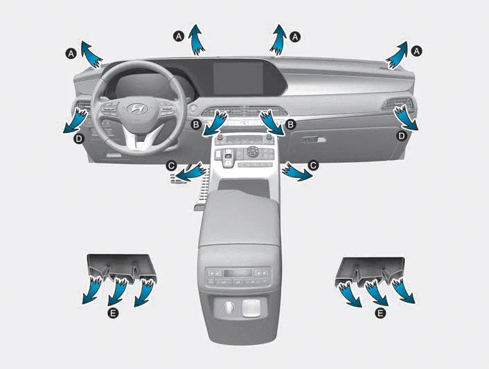
The air flow outlet direction is cycled as follows:

Face-Level (B, D)

Air flow is directed toward the upper body and face. Additionally, each outlet can be controlled to direct the air discharged from the outlet.
Bi-Level (B, C, D, E)

Air flow is directed towards the face and the floor.
Floor & Defrost (A, C, D, E)

Most of the air flow is directed to the floor and the windshield with a small amount directed to the side window defrosters.
Floor-Level (A, C, D, E)

Most of the air flow is directed to the floor, with a small amount of the air being directed to the windshield and side window defrosters.
Defrost-Level (6) (A, D)
Most of the air flow is directed to the windshield with a small amount of air directed to the side window defrosters.
The heating and cooling system can be controlled manually by pushing buttons other than the AUTO button. In this case, the system works sequentially according to the order of buttons selected.
Instrument panel vents The instrument panel vent air flow can be directed up/down or left/right using the vent adjustment lever. The outlet vents can be opened or closed separately using the vent control lever.
Other information:
Hyundai Palisade (LX2) 2020-2026 Service Manual: Description and operation
Hyundai Palisade (LX2) 2020-2026 Service Manual: Description and operation
Description Rear view camera will activate when the backup light is ON with the ignition switch ON and the shift lever in the R position. This system is a supplemental system that shows behind the vehicle through the AV monitor or the ECM (Reverse Display Room Mirror) mirror while backing-up.
Categories
- Manuals Home
- Hyundai Palisade Owners Manual
- Hyundai Palisade Service Manual
- Electronic Child Safety Lock System
- Lift and Support Points
- Engine Mechanical System
- New on site
- Most important about car
