Hyundai Palisade (LX2): Manual climate control system / System Maintenance
Cabin air filter
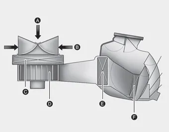
[A] : Outside air, [B] : Recirculated air, [C] : Climate control air filter, [D] : Blower, [E] : Evaporator core, [F] : Heater core
The cabin air filter is installed behind the glove box. It filters the dust or other pollutants that enter the vehicle through the heating and air conditioning system.
Have the cabin air filter replaced by an authorized HYUNDAI dealer according to the maintenance schedule. If the vehicle is being driven in severe conditions such as dusty or rough roads and/or if transporting pets or occupants smoke inside the vehicle, then more frequent cabin air filter inspections and changes are required.
If the air flow rate suddenly decreases, the system should be checked at an authorized HYUNDAI dealer.
Checking the amount of air conditioner refrigerant and compressor lubricant
When the amount of refrigerant is low, the performance of the air conditioning is reduced. Overfilling also reduces the performance of the air conditioning system.
Therefore, if abnormal operation is found, have the system inspected by an authorized HYUNDAI dealer.
NOTICE
It is important that the correct type and amount of oil and refrigerant is used. Otherwise, damage to the compressor and abnormal system operation may occur.
WARNING

Because the refrigerant is at very high pressure, the air conditioning system should only be serviced by trained and certified technicians. It is important that the correct type and amount of oil and refrigerant is used, otherwise damage to the vehicle and personal injury may occur.
The air conditioning system should be serviced by an authorized HYUNDAI dealer.
Air Conditioning refrigerant label
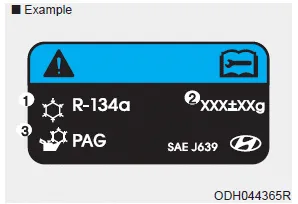
The actual Air Conditioning refrigerant label in the vehicle may differ from the illustration.
Each symbols and specification on air conditioning refrigerant label means as below :
1. Classification of refrigerant
2. Amount of refrigerant
3. Classification of Compressor lubricant
Refer to chapter 8 for more detail location of the air conditioning refrigerant label.
Cooling / Ventilation 1. Select the Face Level mode. 2. Set the air intake control to fresh mode. 3. Set the temperature control to the desired position.
Front 1. DriverŌĆÖs temperature control knob 2. PassengerŌĆÖs temperature control knob 3. AUTO (automatic control) button 4. SYNC button 5. OFF button 6.
Other information:
Hyundai Palisade (LX2) 2020-2025 Service Manual: Temperature Control Actuator
Description and operation Description The heater unit includes mode control actuator and temperature control actuator. The temperature control actuator is located at the heater unit. It regulates the temperature by the procedure as follows.
Hyundai Palisade (LX2) 2020-2025 Service Manual: General safety information and caution
General Safety Information and Caution 1. Be careful when driving the vehicle using the smart cruise control system as follows. (1) On curves or inclines/declines ŌĆó The smart cruise control system may have limits to detect
Categories
- Manuals Home
- Hyundai Palisade Owners Manual
- Hyundai Palisade Service Manual
- Scheduled maintenance services
- Specifications
- Automatic Transaxle System (A8LF1)
- New on site
- Most important about car
