Hyundai Palisade: Remote Key / Battery replacement
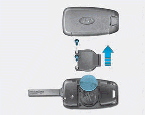
If the remote key is not working properly,
try replacing the battery with a
new one.
Battery Type: CR2032
To replace the battery:
1.Insert a slim tool into the slot and
gently pry open the cover.
2.Using a screw driver, remove the
battery cover.
3.Remove the old battery and insert
the new battery. Make sure the battery
position is correct.
4.Reinstall the battery cover and key
cover in the reverse order of
removal.
If you suspect your remote key might
have sustained some damage, or
you feel your remote key is not working
correctly contact an authorized
HYUNDAI dealer.
Information
An inappropriately disposed
battery can be harmful to the
environment and human health.
Dispose of the battery according
to your local law(s) or regulations.
The remote key will not work if any of
the following occur:
The key is in the ignition switch.
You exceed the operating distance
limit (about 90 feet [30 m])...
■ Type A
■ Type B
Your HYUNDAI uses a Smart Key,
which you can use to lock or unlock
the driver and passenger doors or
the rear liftgate.
1.Door Lock
2...
Other information:
Schematic diagrams
ECM Terminal and Input /
Output Signal
ECM Terminal Function
Connector [A]
Pin No
Description
Connected to
1
Ignition Coil (Cylinder #4) control output
Ignition Coil (Cylinder #4)
2
Injector (Cylinder #3) [High] control output
Injector (Cylinder #3)
3
Injector (Cylinder #5) [High] control output
Injector (Cylinder #5)
4
Injector (Cylinder #1) [High] control output
Injector (Cylinder #1)
5
Camshaft Position Sensor (CMPS) [Bank 2 / Exhaust] signal input
Camshaft Position Sensor (CMPS) [Bank 2 / Exhaust]
6
Camshaft Position Sensor (CMPS) [Bank 2 / Intake] signal input
Camshaft Position Sensor (CMPS) [Bank 2 / Intake]
7
Throttle Position Sensor (TPS) 2 signal input
Throttle Position Sensor (TPS) 2
8
-
9
Rail Pressure Sensor (RPS) signal input
Rail Pressure Sensor (RPS)
10
CVVT Oil Temperature Sensor (OTS) signal input
CVVT Oil Temperature Sensor (OTS)
11
-
12
-
13
Sensor power (+5V)
CVVT Oil Temperature Sensor (OTS)
Manifold Absolute Pressure Sensor (MAPS)
14
-
15
-
16
-
17
-
18
-
19
ETC Motor [-] control output
ETC Motor
20
Heated Oxygen Sensor (HO2S) [Bank 1 / Sensor 1] Heater control output
Heated Oxygen Sensor (HO2S) [Bank 1 / Sensor 1]
21
Heated Oxygen Sensor (HO2S) [Bank 2 / Sensor 1] Heater control output
Heated Oxygen Sensor (HO2S) [Bank 2 / Sensor 1]
22
Ignition Coil (Cylinder #5) control output
Ignition Coil (Cylinder #5
23
Injector (Cylinder #6) [High] control output
Injector (Cylinder #6)
24
Injector (Cylinder #2) [High] control output
Injector (Cylinder #2)
25
Injector (Cylinder #4) [High] control output
Injector (Cylinder #4)
26
Camshaft Position Sensor (CMPS) [Bank 1 / Exhaust] signal input
Camshaft Position Sensor (CMPS) [Bank 1 / Exhaust]
27
Camshaft Position Sensor (CMPS) [Bank 1 / Intake] signal input
Camshaft Position Sensor (CMPS) [Bank 1 / Intake]
28
Intake Air Temperature Sensor (IATS) signal input
Intake Air Temperature Sensor (IATS)
29
Manifold Absolute Pressure Sensor (MAPS) signal input
Manifold Absolute Pressure Sensor (MAPS)
30
-
31
-
32
-
33
-
34
Sensor power (+5V)
Camshaft Position Sensor (CMPS) [Bank 1 / Exhaust]
Camshaft Position Sensor (CMPS) [Bank 2 / Intake]
35
-
36
Sensor power (+5V)
Camshaft Position Sensor (CMPS) [Bank 1 / Intake]
Camshaft Position Sensor (CMPS) [Bank 2 / Exhaust]
37
-
38
Purge Control Solenoid Valve (PCSV) control output
Purge Control Solenoid Valve (PCSV)
39
-
40
ETC Motor [+] control output
ETC Motor
41
-
42
-
43
Ignition Coil (Cylinder #1) control output
Ignition Coil (Cylinder #1)
44
Injector (Cylinder #6) [Low] control output
Injector (Cylinder #6)
45
Injector (Cylinder #3) [Low] control output
Injector (Cylinder #3)
46
Injector (Cylinder #2) [Low] control output
Injector (Cylinder #2)
47
Sensor ground
Camshaft Position Sensor (CMPS) [Bank 1 / Exhaust]
Camshaft Position Sensor (CMPS) [Bank 2 / Intake]
48
Sensor ground
Manifold Absolute Pressure Sensor (MAPS)
Oil Pressure Sensor (OPS)
49
Sensor ground
Camshaft Position Sensor (CMPS) [Bank 1 / Intake]
Camshaft Position Sensor (CMPS) [Bank 2 / Exhaust]
50
-
51
-
52
-
53
-
54
Engine Coolant Temperature Sensor (ECTS) signal input
Engine Coolant Temperature Sensor (ECTS)
55
Sensor Shield
Crankshaft Position Sensor (CKPS)
Knock Sensor (KS) #1 [Bank 1]
Knock Sensor (KS) #2 [Bank 2]
56
Sensor power (+5V)
Rail Pressure Sensor (RPS)
57
-
58
Sensor ground
Engine Coolant Temperature Sensor (ECTS)
Rail Pressure Sensor (RPS)
59
Sensor ground
Throttle Position Sensor (TPS) 1
Throttle Position Sensor (TPS) 2
60
Variable Intake Solenoid (VIS) Valve 1 control output
Variable Intake Solenoid (VIS) Valve 1
61
Variable Intake Solenoid (VIS) Valve 2 control output
Variable Intake Solenoid (VIS) Valve 2
62
-
63
-
64
Ignition Coil (Cylinder #2) control output
Ignition Coil (Cylinder #2)
65
Injector (Cylinder #1) [Low] control output
Injector (Cylinder #1)
66
Injector (Cylinder #4) [Low] control output
Injector (Cylinder #4)
67
Injector (Cylinder #5) [Low] control output
Injector (Cylinder #5)
68
Crankshaft Position Sensor (CKPS) [High] signal input
Crankshaft Position Sensor (CKPS)
69
Crankshaft Position Sensor (CKPS) [Low] signal input
Crankshaft Position Sensor (CKPS)
70
-
71
-
72
Oil pressure switch signal input
Oil Pressure Sensor (OPS)
73
-
74
-
75
Throttle Position Sensor (TPS) 1 signal input
Throttle Position Sensor (TPS) 1
76
Knock Sensor (KS) [Bank 1] [Low] signal input
Knock Sensor (KS) [Bank 1]
77
Knock Sensor (KS) [Bank 2] [Low] signal input
Knock Sensor (KS) [Bank 2]
78
Sensor ground
Heated Oxygen Sensor (HO2S) [Bank 2 / Sensor 2]
79
Rc/Rp (Pump Cell Voltage)
Heated Oxygen Sensor (HO2S) [Bank 2 / Sensor 1]
80
VS+ (NERNST Cell Voltage)
Heated Oxygen Sensor (HO2S) [Bank 2 / Sensor 1]
81
Heated Oxygen Sensor (HO2S) [Bank 2 / Sensor 2] signal input
Heated Oxygen Sensor (HO2S) [Bank 2 / Sensor 2]
82
VS+ (NERNST Cell Voltage)
Heated Oxygen Sensor (HO2S) [Bank 1 / Sensor 1]
83
Rc (Compensative Resistance)
Heated Oxygen Sensor (HO2S) [Bank 1 / Sensor 1]
84
Oil Pressure Solenoid Valve control output
Oil Pressure Solenoid Valve
85
Ignition Coil (Cylinder #6) control output
Ignition Coil (Cylinder #6)
86
Ignition Coil (Cylinder #3) control output
Ignition Coil (Cylinder #3)
87
Fuel Pressure Control Valve (FPCV) [High] control output
Fuel Pressure Control Valve (FPCV)
88
Fuel Pressure Control Valve (FPCV) [Low] control output
Fuel Pressure Control Valve (FPCV)
89
Heated Oxygen Sensor (HO2S) [Bank 2 / Sensor 2] Heater control output
Heated Oxygen Sensor (HO2S) [Bank 2 / Sensor 2]
90
Heated Oxygen Sensor (HO2S) [Bank 1 / Sensor 2] Heater control output
Heated Oxygen Sensor (HO2S) [Bank 1 / Sensor 2]
91
CVVT Oil Control Valve (OCV) [Bank 2 / Exhaust] control output
CVVT Oil Control Valve (OCV) [Bank 2 / Exhaust]
92
CVVT Oil Control Valve (OCV) [Bank 1 / Exhaust] control output
CVVT Oil Control Valve (OCV) [Bank 1 / Exhaust]
93
Variable Force Solenoid (VFS) [Bank 2 / Intake] control output
Variable Force Solenoid (VFS) [Bank 2 / Intake]
94
Variable Force Solenoid (VFS) [Bank 1 / Intake] control output
Variable Force Solenoid (VFS) [Bank 1 / Intake]
95
-
96
Sensor power (+5V)
Throttle Position Sensor (TPS) 1
Throttle Position Sensor (TPS) 2
97
Knock Sensor (KS) [Bank 1] [High] signal input
Knock Sensor (KS) [Bank 1]
98
Knock Sensor (KS) [Bank 2] [High] signal input
Knock Sensor (KS) [Bank 2]
99
Sensor ground
Heated Oxygen Sensor (HO2S) [Bank 1 / Sensor 2]
100
-
101
Rc (Compensative Resistance)
Heated Oxygen Sensor (HO2S) [Bank 2 / Sensor 1]
102
VS-/IP- (Common ground)
Heated Oxygen Sensor (HO2S) [Bank 2 / Sensor 1]
103
Heated Oxygen Sensor (HO2S) [Bank 1 / Sensor 2] signal input
Heated Oxygen Sensor (HO2S) [Bank 1 / Sensor 2]
104
VS-/IP- (Common ground)
Heated Oxygen Sensor (HO2S) [Bank 1 / Sensor 1]
105
Rc/Rp (Pump Cell Voltage)
Heated Oxygen Sensor (HO2S) [Bank 1 / Sensor 1]
Connector [K]
Pin No
Description
Connected to
1
ECM ground
Chassis ground
2
ECM ground
Chassis ground
3
Battery power (B+)
Main Relay
4
ECM ground
Chassis ground
5
Battery power (B+)
Main Relay
6
Battery power (B+)
Main Relay
7
-
8
-
9
-
10
-
11
-
12
-
13
Sensor ground
A/C Pressure Transducer (APT)
14
Immobilizer communication line
Immobilizer Control Module
15
Fuel Level Sender (FLS) signal input [Fuel pump]
Fuel Level Sender (FLS)
16
-
17
-
18
-
19
-
20
Sensor power (+5V)
Accelerator Position Sensor (APS) 1
21
Main Relay control output
Main Relay
22
-
23
-
24
-
25
-
26
-
27
-
28
Accelerator Position Sensor (APS) 2 signal input
Accelerator Position Sensor (APS) 2
29
-
30
-
31
-
32
Fuel Level Sender (FLS) signal input [Sub Fuel Sender]
Sub Fuel Level Sender
33
Fuel Pump Relay control output
Fuel Pump Relay
34
-
35
Sensor power (+5V)
A/C Pressure Transducer (APT)
36
Sensor power (+5V)
Accelerator Position Sensor (APS) 2
37
-
38
Vehicle speed signal input
VDC control module
39
-
40
-
41
Start signal input
Start Relay
42
-
43
-
44
-
45
-
46
-
47
Sensor ground
Accelerator Position Sensor (APS) 2
48
-
49
Brake Switch [Test] signal input
Brake Switch
50
-
51
-
52
Sensor ground
Accelerator Position Sensor (APS) 1
53
-
54
-
55
-
56
-
57
-
58
-
59
-
60
P-CAN [Low]
Other control module, Data Link Connector (DLC), Multi-Purpose Check Connector
61
-
62
-
63
-
64
A/C Pressure Transducer (APT) signal input
A/C Pressure Transducer (APT)
65
-
66
-
67
-
68
-
69
LIN (Local Interconnect Network) Serial Bus Line
Battery Sensor
70
-
71
Cooling Fan Relay control output
Cooling Fan Relay
72
Engine speed signal output
Integrated Body Control Unit (IBU)
73
-
74
-
75
-
76
-
77
P-CAN [High]
Other control module, Data Link Connector (DLC), Multi-Purpose Check Connector
78
-
79
Start Relay control output
Start Relay
80
-
81
-
82
Accelerator Position Sensor (APS) 1 signal input
Accelerator Position Sensor (APS) 1
83
Brake Switch [Light] signal input
Brake Switch
84
-
85
-
86
-
87
-
88
-
89
-
90
-
91
-
ECM Terminal Input/ Output signal
Connector [A]
Pin No
Description
Condition
Type
Level
1
Ignition Coil (Cylinder #4) control output
Idle
Pulse
Vpeak = 400V
Frequency : 0 - 58...
■ Type A and B
■ Type C
This gauge indicates the temperature
of the engine coolant when the
ignition switch is in the ON position.
NOTICE
If the gauge pointer moves
beyond the normal range area
toward the "H" position, it indicates
overheating that may damage
the engine...
Categories
To lock your vehicle using the door
handle button or the Smart Key:
1.Make sure all doors, the hood and
the liftgate are closed.
2.Make sure you have the smart key
in your possession.
read more