Hyundai Palisade (LX2): Seat Electrical / Seat Heater (Air Ventilation)
Components and components location
| Components |
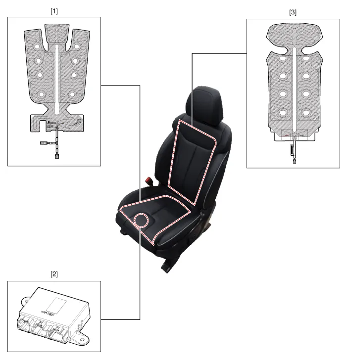
| 1. Seat cushion heater 2. Seat heater unit (Passenger only) |
3. Seat back heater |
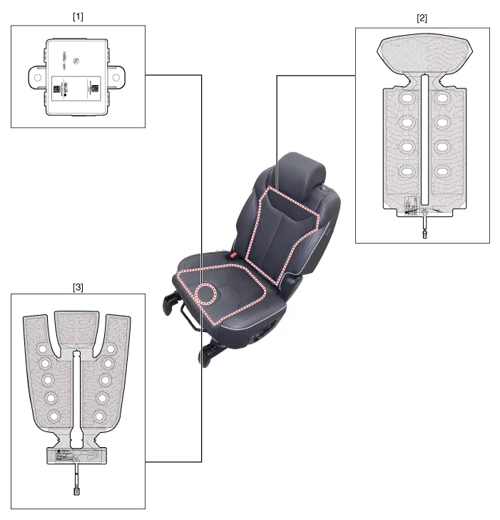
| 1. Seat heater unit (Passenger
only) 2. Seat cushion heater |
3. Seat back heater |
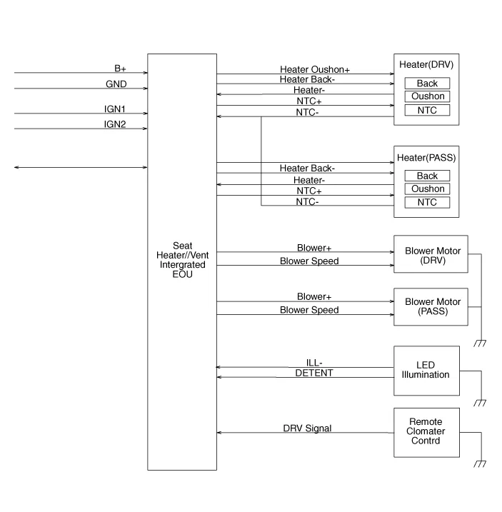
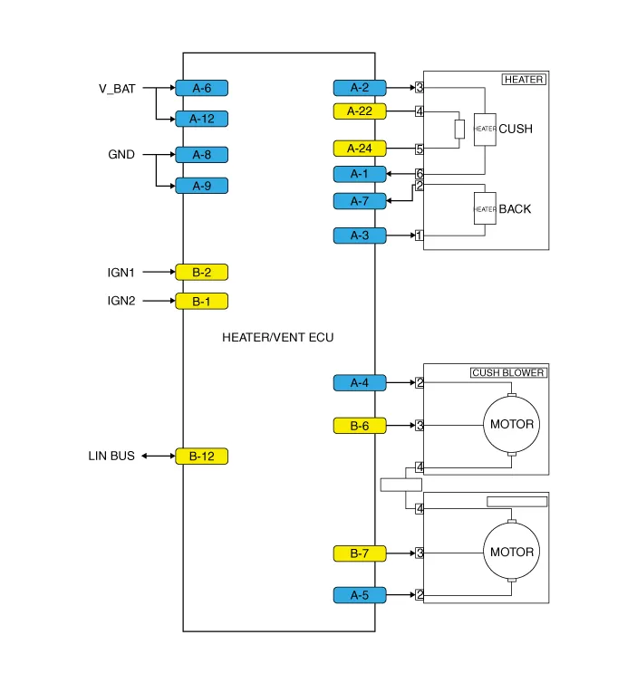
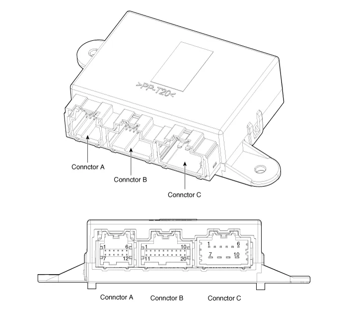
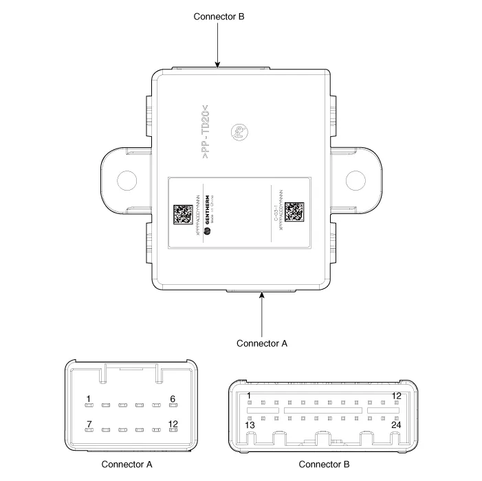
Schematic diagrams
| Circuit Diagram |
|
No |
Connector A |
Connector B |
Connector C |
|
1 |
- |
- |
Driver cushion heater |
|
2 |
- |
- |
Driver back heater |
|
3 |
- |
- |
Assist cushion heater |
|
4 |
DETENT |
- |
Assist back heater |
|
5 |
Illumination |
- |
Driver blower |
|
6 |
Driver vent control PWM |
LIN |
Assist blower |
|
7 |
Assist heater power |
- |
Battery (+) |
|
8 |
Driver heater power |
- |
Driver heater (-) |
|
9 |
- |
- |
Ground |
|
10 |
- |
IGN 1 |
Assist heater (-) |
|
11 |
- |
- |
|
|
12 |
- |
- |
|
|
13 |
|
- |
|
|
14 |
- |
||
|
15 |
- |
||
|
16 |
- |
||
|
17 |
NTC (-) |
||
|
18 |
Assist NTC (+) |
||
|
19 |
Driver NTC (+) |
||
|
20 |
IGN 2 |
|
No |
Connector A |
Connector B |
|
1 |
Heater (-) |
Heater vent unit IGN 2 |
|
2 |
Cushion heater power |
Heater vent unit IGN 1 |
|
3 |
Seat back heater power |
- |
|
4 |
Cushion blower power |
- |
|
5 |
Seat back blower power |
- |
|
6 |
Heater vent power |
Cushion blower VSP |
|
7 |
Heater (-) |
Seat back blower VSP |
|
8 |
Heater vent ground |
- |
|
9 |
Heater vent ground |
- |
|
10 |
- |
- |
|
11 |
- |
- |
|
12 |
Heater vent Power |
LIN |
|
13 |
|
- |
|
14 |
- |
|
|
15 |
- |
|
|
16 |
- |
|
|
17 |
- |
|
|
18 |
- |
|
|
19 |
- |
|
|
20 |
- |
|
|
21 |
- |
|
|
22 |
NTC (+) |
|
|
23 |
- |
|
|
24 |
NTC (-) |
Repair procedures
| Inspection |
| 1. |
Check for continuity and measure the resistance between terminals.
|
| 2. |
Operate the seat heater after connecting the connector, and then check
the thermostat by measuring the temperature of seat surface.
|
| 1. |
Check for continuity and measure the resistance between terminals.
|
Components and components location Components Driver/Passenger Seat Heater 1. Seat cushion heater 2. Seat heater unit (Passenger only) 3.
Components and components location Components (1) Front seat 1. Air ventilation seat blower 2. Air ventilation seat control unit (Passenger only) 3.
Other information:
Hyundai Palisade (LX2) 2020-2026 Service Manual: PTC Heater (Diesel only)
Description and operation Description The PTC (Positive Temperature Coefficient) heater is installed at the exit or the backside of the heater core. The PTC heater is an electric heater using a PTC element as an auxiliary heating device that supplements deficiency of interior heat source in highly effective diesel engi
Hyundai Palisade (LX2) 2020-2026 Service Manual: Cruise Control (CC) Switch
Components and components location Components 1. Remote control switch (Audio swtich) 2. Remote control switch (Cruise control switch) Schematic diagrams Circuit Diagram Repair procedures Removal 1.
Categories
- Manuals Home
- Hyundai Palisade Owners Manual
- Hyundai Palisade Service Manual
- Automatic Transaxle System (A8LF1)
- Automatic Transaxle Fluid (ATF)
- Rain Sensor
- New on site
- Most important about car
