Hyundai Palisade (LX2): Seat Electrical / Seat Heater (Non-Air Ventilation)
Components and components location
| Components |

| 1. Seat cushion heater 2. Seat heater unit (Passenger only) |
3. Seat back heater |
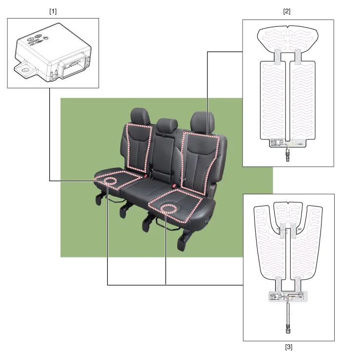
| 1. Seat heater unit 2. Seat back heater |
3. Seat cushion heater |
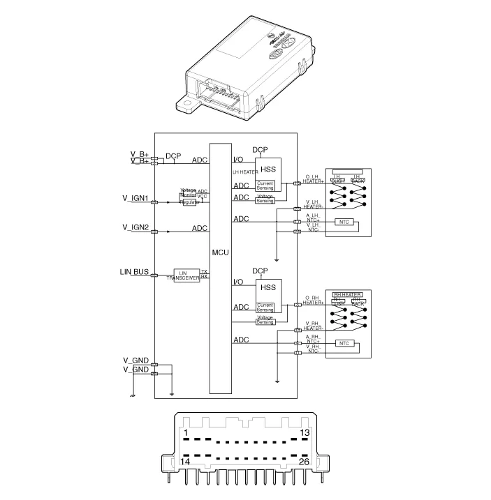
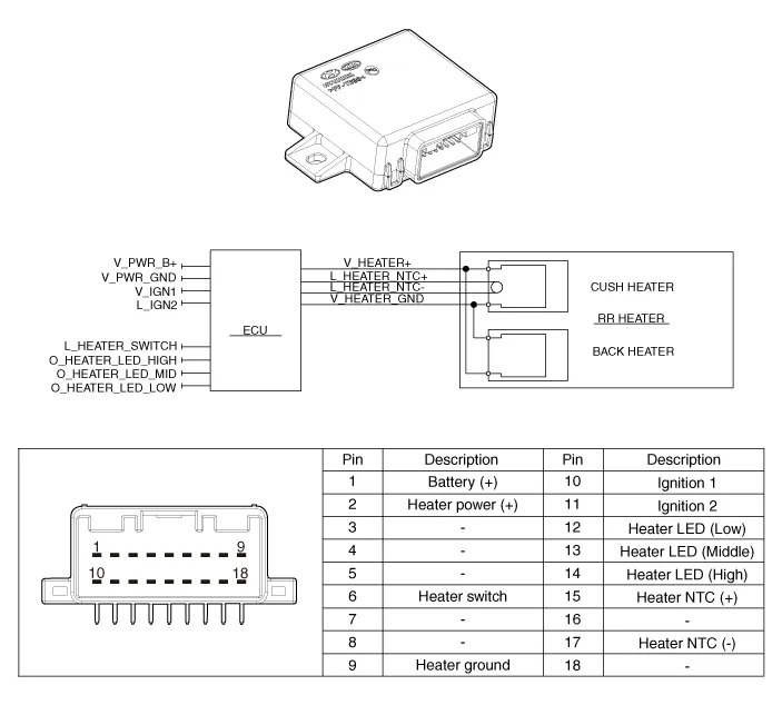
Schematic diagrams
| Components |
Repair procedures
| Inspection |
| 1. |
Check for continuity and measure the resistance between terminals.
|
| 2. |
Operate the seat heater after connecting the connector, and then check
the thermostat by measuring the temperature of seat surface.
|
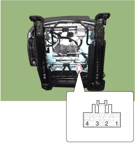
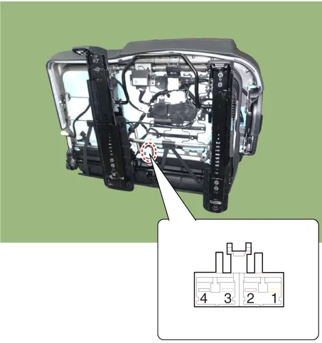
| 1. |
Check for continuity and measure the resistance between terminals.
[RH]
[LH]
|
| 2. |
Operate the seat heater after connecting the connector, and then check
the thermostat by measuring the temperature of seat surface.
|
Components and components location Components 1. Front seat heater switch 2. Rear seat heater switch Schematic diagrams Circuit Diagram Front Seat No Connector A 1 C_CAN (High) 2 C_CAN (Low) 3 - 4 LIN 5 - 6 Auto hold signal 7 - 8 Battery (+) 9 IGN 10 Illumination (+) 11 - 12 Illumination (-) 13 Ground 14 DETENT 15 - 16 PDW signal 17 Steering wheel heater signal 18 DBC signal 19 ISG signal 20 SVM/RVM signal 21 ISG indicator 22 SVM indicator 23 PDW indicator 24 Steering whell heater indicator 2nd Seat No Connector A 1 Battery (+) 2 ISG Power(+) 3 Illumination (+) 4 Sensor REF (+5V) 5 Mode actuator feadback 6 Temperature actuator feedback 7 Mode actuator (Vent) 8 Mode actuator (Defrost) 9 Temperature actuator (Cooling) 10 Temperature actuator (Heating) 11 DETENT (-) 12 K-LINE 13 LIN line (Rear left seat) 14 LIN line (Rear right seat 15 - 16 Illumination (-) 17 IGN 2 18 IGN 1 19 Blower motor (+) 20 - 21 Rear FET (Drain feedback) 22 Rear FET (Gate) 23 Left heater swtich 24 Left heater indicator (High) 25 Left heater indicator (Middle) 26 Left heater indicator (Low) 27 Right heater swtich 28 Right heater indicator (High) 29 Right heater indicator (Middle) 30 Right heater indicator (Low) 31 Sensor ground 32 Ground Repair procedures Removal Front seat 1.
Components and components location Components Driver/Passenger Seat Heater 1. Seat cushion heater 2. Seat heater unit (Passenger only) 3.
Other information:
Hyundai Palisade (LX2) 2020-2026 Service Manual: General safety information and caution
Instructions (R-134a) When Handling Refrigerant 1. R-134a liquid refrigerant is highly volatile. A drop on the skin of your hand could result in localized frostbite. When handling the refrigerant, be sure to wear gloves.
Hyundai Palisade (LX2) 2020-2026 Service Manual: Heater & A/C Control Unit (DATC)
Components and components location Component Connector Pin Function Connector PIN No Pin Function Connector PIN No Pin Function A 1 Battery A 21 IGN2 2
Categories
- Manuals Home
- Hyundai Palisade Owners Manual
- Hyundai Palisade Service Manual
- Power Outlet
- Rear Bumper Cover
- Body (Interior and Exterior)
- New on site
- Most important about car
