
Hyundai Palisade (LX2): Coupling Assembly / Oil hydraulic Motor(Actuator)
Description and operation
| Description |
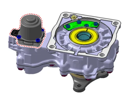
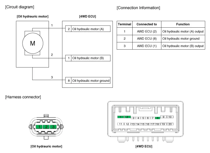
Schematic diagrams
| Circuit Diagram |
Repair procedures
| Inspection |
|

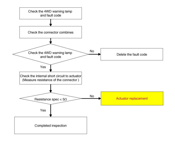
| Oil Hydraulic Motor (Actuator) Inspection Procedure |
| Removal |
| 1. |
Remove the coupling assembly.
(Refer to 4 Wheel Drive (AWD) System - "Coupling Assembly")
|
| 2. |
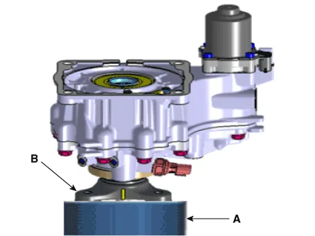
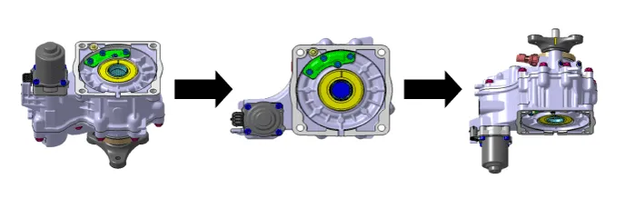
Keep going perpendicular state after remove the coupling assembly.
|

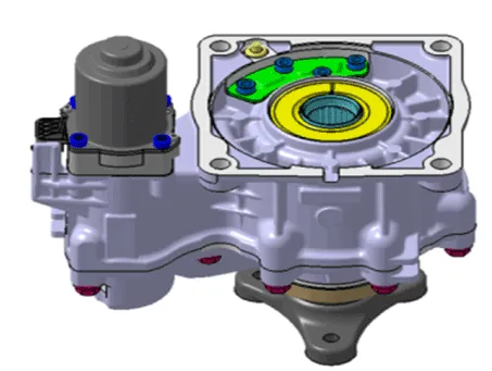
| 3. |
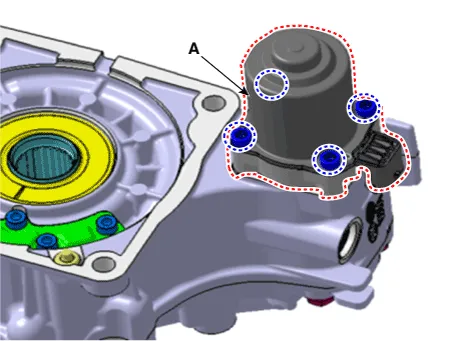
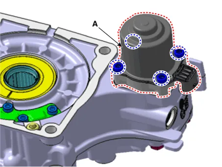
Remove the hydraulic motor (A) after loosening bolts with hex wrench.
|


| Installation |
| 1. |
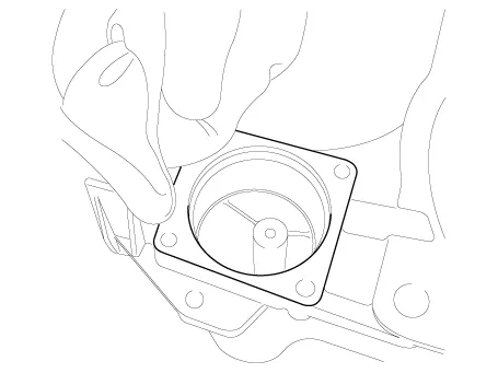
Before installation, wipe the surface with a clean cloth.
|
| 2. |
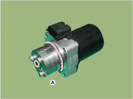
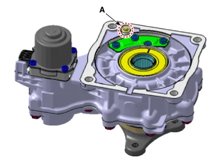
Check the O-rings (A) of the new hydraulic motor (actuators).
|

| 3. |
Tighten the bolts after install the hydraulic motor.
|


| 4. |
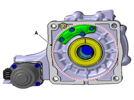
Wipe the flowed oil to around the surface (A) with a clean cloth.
|
| 5. |
Install the coupling assembly.
(Refer to 4 Wheel Drive (AWD) System - "Coupling Assembly")
|
Components and components location Component Location 1. Trasaxle assembly 2. Transfer assembly 3. Propeller shaft assembly 4.
Description and operation Description The AWD ECU makes a Motor Pump(Actuator) turn round for generating an oil pressure. And then it presses a multiple disk clutch and transfers the generated torque into rear wheels.
Other information:
Hyundai Palisade (LX2) 2020-2026 Service Manual: Repair procedures
Refrigerant System Service Basics (R-134a) Refrigerant Recovery Use only service equipment that is U.L-listed and is certified to meet the requirements of SAE J2210 to remove HFC-134a(R-134a) from the air conditioning system.
Hyundai Palisade (LX2) 2020-2026 Service Manual: Refrigerant Line
Components and components location Components [Isometric view] 1. Front suction & Liquid pipe assembly [Top view] 1. Front suction & Liquid pipe assembly Repair procedures Replacement [Front suction & Liquid pipe assem
Categories
- Manuals Home
- Hyundai Palisade Owners Manual
- Hyundai Palisade Service Manual
- Automatic Transaxle Fluid (ATF)
- Electronic Child Safety Lock System
- Automatic Transaxle System (A8LF1)
- New on site
- Most important about car
