Hyundai Palisade (LX2): Cylinder Head Assembly / Cylinder Head
Components and components location
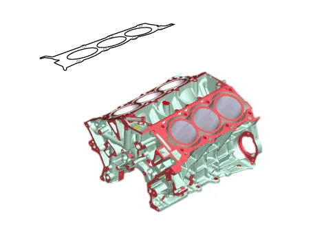
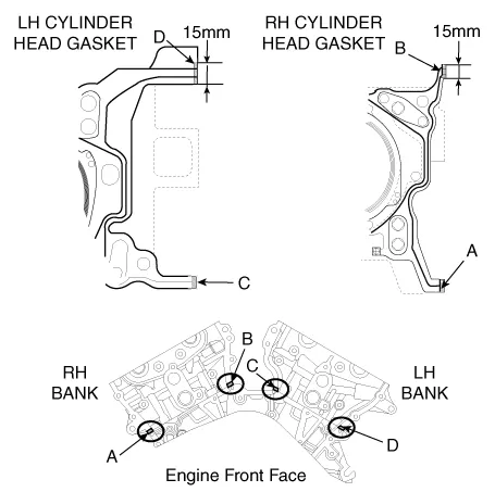
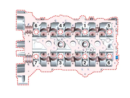
| Components |
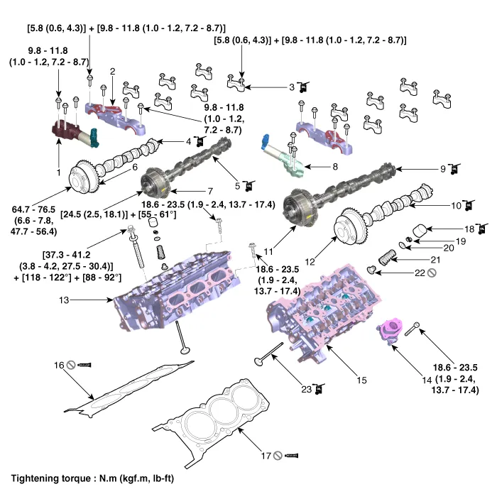
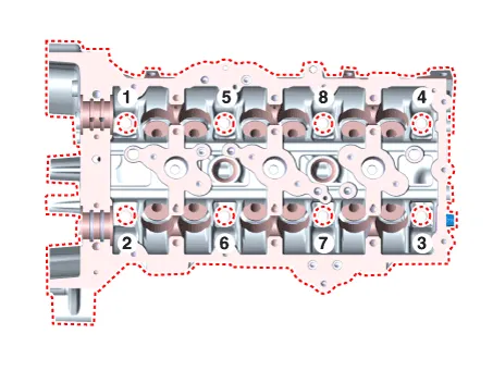
| 1. RH intake camshaft OCV 2. Camshaft thrust bearing cap 3. Camshaft bearing cap 4. RH exhaust camshaft 5. RH intake camshaft 6. RH exhaust camshaft CVVT assembly 7. RH intake camshaft CVVT assembly 8. LH exhaust camshaft OCV |
9. LH intake camshaft 10. LH exhaust camshaft 11. LH intake camshaft CVVT assembly 12. LH exhaust camshaft CVVT assembly 13. RH cylinder head 14. Fuel pump bracket 15. LH cylinder head 16. RH cylinder head gasket |
17. LH cylinder head gasket 18. MLA 19. Retainer lock 20. Retainer 21. Valve spring 22. Valve stem seal 23. Valve |
Repair procedures
| Removal |
|

|

|

| 1. |
Remove the air duct.
(Refer to Intake and Exhaust System - "Air Cleaner")
|
| 2. |
Remove the battery.
(Refer to Engine Electrical System - "Battery")
|
| 3. |
Remove the engine cover.
(Refer to Engine and Transaxle Assembly - "Engine Cover")
|
| 4. |
Remove the air cleaner assembly.
(Refer to Intake and Exhaust System - "Air Cleaner")
|
| 5. |
Remove the engine room under cover.
(Refer to Engine and Transaxle Assembly - "Engine Room Under Cover")
|
| 6. |
Drain the engine coolant.
(Refer to Cooling System - "Coolant")
|
| 7. |
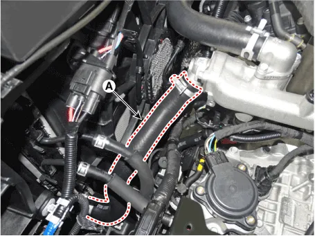
Disconnect the radiator upper hose (A).
|
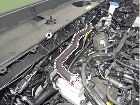
| 8. |
Disconnect the radiator lower hose (A).
|
| 9. |
Remove the surge tank.
(Refer to Intake and Exhaust System - "Surge Tank")
|
| 10. |
Remove the intake manifold.
(Refer to Intake and Exhaust System - "Intake Manifold")
|
| 11. |
Remove the RH exhaust manifold.
(Refer to Intake and Exhaust System - "Exhaust Manifold")
|
| 12. |
Remove the RH cylinder head cover.
(Refer to Cylinder Head Assembly - "Cylinder Head Cover")
|
| 13. |
Remove the timing chain.
(Refer to Timing System - "Timing Chain")
|
| 14. |
Remove the water temperature control assembly.
(Refer to Cooling System - "Water Temperature Control Assembly")
|
| 15. |
Remove the RH camshaft.
(Refer to Cylinder Head Assembly - "CVVT & Camshaft")
|
| 16. |
Remove the delivery pipe.
(Refer to Engine Control / Fuel System - "Delivery Pipe")
|
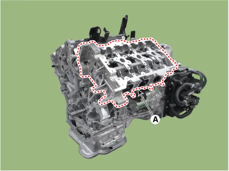
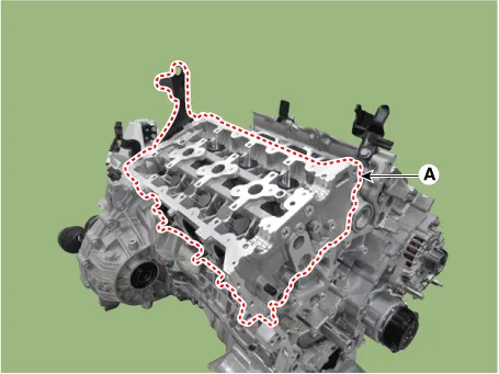
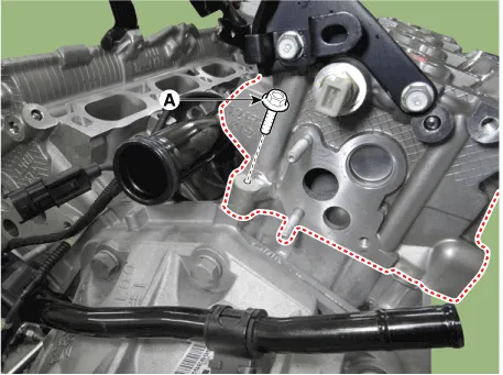
| 17. |
Remove the RH cylinder head.
|


| 18. |
Remove the air duct.
(Refer to Intake and Exhaust System - "Air Cleaner")
|
| 19. |
Remove the battery.
(Refer to Engine Electrical System - "Battery")
|
| 20. |
Remove the engine cover.
(Refer to Engine and Transaxle Assembly - "Engine Cover")
|
| 21. |
Remove the air cleaner assembly.
(Refer to Intake and Exhaust System - "Air Cleaner")
|
| 22. |
Remove the engine room under cover.
(Refer to Engine and Transaxle Assembly - "Engine Room Under Cover")
|
| 23. |
Drain the engine coolant.
(Refer to Cooling System - "Coolant")
|
| 24. |
Disconnect the radiator upper hose (A).
|

| 25. |
Disconnect the radiator lower hose (A).
|

| 26. |
Remove the surge tank.
(Refer to Intake and Exhaust System - "Surge Tank")
|
| 27. |
Remove the intake manifold.
(Refer to Intake and Exhaust System - "Intake Manifold")
|
| 28. |
Remove the LH exhaust manifold.
(Refer to Intake and Exhaust System - "Exhaust Manifold")
|
| 29. |
Remove the alternator.
(Refer to Engine Electrical System - "Alternator")
|
| 30. |
Remove the LH cylinder head cover.
(Refer to Cylinder Head Assembly - "Cylinder Head Cover")
|
| 31. |
Remove the timing chain.
(Refer to Timing System - "Timing Chain")
|
| 32. |
Remove the water temperature control assembly.
(Refer to Cooling System - "Water Temperature Control Assembly")
|
| 33. |
Remove the LH camshaft.
(Refer to Cylinder Head Assembly - "CVVT & Camshaft")
|
| 34. |
Remove the delivery pipe.
(Refer to Engine Control / Fuel System - "Delivery Pipe")
|
| 35. |
Remove the LH cylinder head.
|


| Disassembly |
|

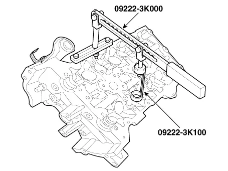
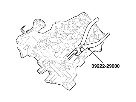
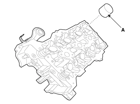
| 1. |
Remove the MLAs (A).
|

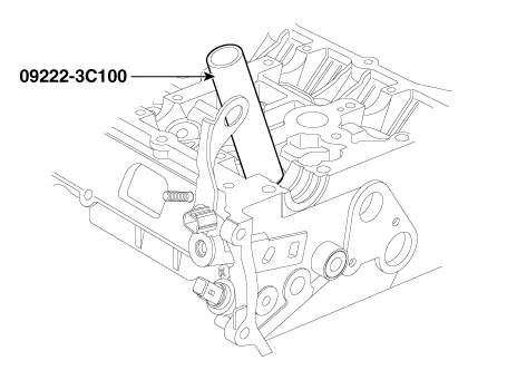
| 2. |
Remove the valves.
|

| Inspection |
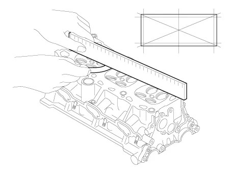
| 1. |
Inspect for flatness.
Using a precision straight edge and feeler gauge, measure the warpage
of the surface contacting with the cylinder block
|
| 2. |
Inspect for cracks.
Check the combustion chamber, intake ports, exhaust ports and cylinder
block surface for cracks. If cracked, replace the cylinder head.
|
| 1. |
Inspect valve stems and valve guides.
|
| 2. |
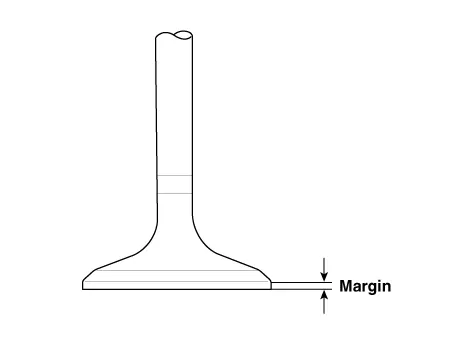
Inspect valves.
|
| 3. |
Inspect valve seats
Check the valve seat for evidence of overheating and improper contact
with the valve face.
If the valve seat is worn, replace cylinder head.
Before reconditioning the seat, check the valve guide for wear. If the
valve guide is worn, replace cylinder head. Recondition the valve seat
with a valve seat grinder or cutter. The valve seat contact width should
be within specifications and centered on the valve face.
|
| 4. |
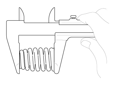
Inspect valve springs.
|
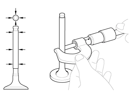
| 1. |
Inspect MLAs.
Using a micrometer, measure the MLA outer diameter.
|
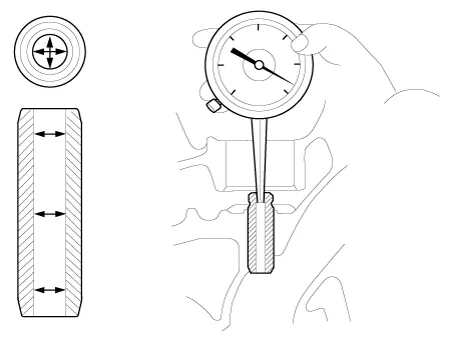
| 2. |
Using a caliper gauge, measure MLA tappet bore inner diameter of cylinder
head.
|
| 3. |
Subtract MLA outer diameter measurement from tappet bore inner diameter
measurement.
|
| Reassembly |
|

| 1. |
Install the valves.
|


| 2. |
Install the MLAs (A).
Check by hand that the MLA rotates smoothly.
|

| Installation |
|

| 1. |
Install the cylinder RH head.
|


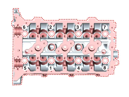
| 2. |
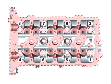
Install the RH cylinder head bolts.
|

| 3. |
Install the remaining parts in the reverse order of removal.
|

| 4. |
Install the cylinder LH head.
|


| 5. |
Install the LH cylinder head bolts.
|

| 6. |
Install the remaining parts in the reverse order of removal.
|

Components and components location Components 1. RH exhaust CVVT 2. RH intake CVVT 3. LH intake CVVT 4. LH exhaust CVVT Repair procedures Removal • Be careful not to damage the parts located under the vehicle (floor under cover, fuel filter, fuel tank and canister) when raising the vehicle using the lift.
Other information:
Hyundai Palisade (LX2) 2020-2026 Service Manual: Evaporator Core
Repair procedures Replacement 1. Disconnect the negative (-) battery terminal. 2. Remove the heater and blower assembly. (Refer to Heater - "Heater Unit") 3.
Hyundai Palisade (LX2) 2020-2026 Service Manual: Rear Evaporator Core
Repair procedures Replacement 1. Remove the rear heater & A/C unit. (Refer to Rear Heater - "Rear Heater Unit") 2. Loosen the mounting screws, remove the rear heater & A/C unit cover (A) and evaporator core (B).
Categories
- Manuals Home
- Hyundai Palisade Owners Manual
- Hyundai Palisade Service Manual
- Components and components location
- How to reset the power liftgate
- Rear Heater Unit
- New on site
- Most important about car
