Hyundai Palisade (LX2): Brake System / Brake bleeding procedures
Hyundai Palisade (LX2) 2020-2026 Service Manual / Brake System / Brake bleeding procedures
| Brake System Bleeding |
Nomal Brake System
|

| 1. |
Make sure the brake fluid in the reservoir is at the MAX (upper) level
line.
|
| 2. |
Have someone slowly pump the brake pedal several times, and then apply
pressure.
|
| 3. |
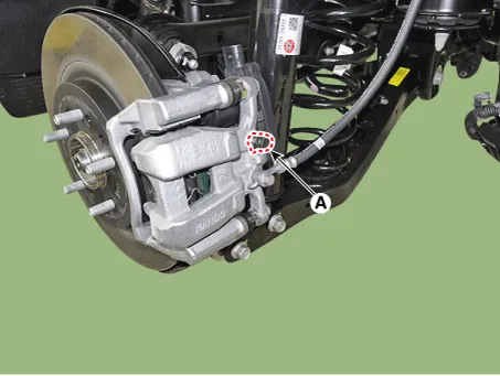
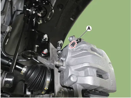
Loosen the right-rear brake bleed screw (A) to allow air to escape from
the system. Then tighten the bleed screw securely.
[Front]
[Rear]
|

| 4. |
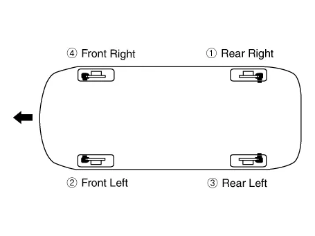
Repeat the procedure for wheel in the sequence shown below until air
bubbles no longer appear in the fluid.
|
| 5. |
Follow the sequence as shown below.
|

| 6. |
Refill the master cylinder reservoir to MAX (upper) level line.
|
ESC Bleeding of Brake System
|

This procedure should be followed to ensure adequate bleeding of air and filling
of the ESC unit, brake lines and master cylinder with brake fluid.
| 1. |
Remove the reservoir cap and fill the brake reservoir with brake fluid.
|

| 2. |
Connect a clear plastic tube to the wheel cylinder bleeder plug and
insert the other end of the tube into a half filled clear plastic bottle.
|
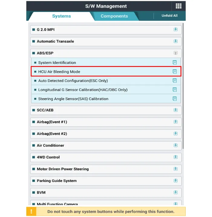
| 3. |
Connect the GDS to the data link connector located underneath the dash
panel.
|
| 4. |
Select and operate according to the instructions on the GDS screen.
|

| 5. |
Have someone slowly pump the brake pedal several times, and then apply
pressure.
|
| 6. |
Pump the brake pedal several times, and then loosen the bleeder screw
until fluid starts to run out without bubbles. Then close the bleeder
screw (A).
[Front]
[Rear]
|

| 7. |
Repeat the procedure for wheel in the sequence shown below until air
bubbles no longer appear in the fluid.
|
| 8. |
Refill the master cylinder reservoir to MAX (upper) level line.
|
Troubleshooting Problem Symptoms Table Use the table below to help you find the cause of the problem. The numbers indicate the priority of the like cause of the problem.
Other information:
Hyundai Palisade (LX2) 2020-2026 Service Manual: Rear Evaporator Core
Repair procedures Replacement 1. Remove the rear heater & A/C unit. (Refer to Rear Heater - "Rear Heater Unit") 2. Loosen the mounting screws, remove the rear heater & A/C unit cover (A) and evaporator core (B).
Hyundai Palisade (LX2) 2020-2026 Service Manual: Description and operation
Description The smart cruise control system allows a driver to program the vehicle to control the speed and following distance by detecting the vehicle ahead without depressing the brake pedal or the accelerator pedal. 1.
Categories
- Manuals Home
- Hyundai Palisade Owners Manual
- Hyundai Palisade Service Manual
- Components and components location
- Lift and Support Points
- Maintenance
- New on site
- Most important about car

Copyright © 2026 www.hpalisadelx.com - 0.0151