Hyundai Palisade (LX2): Automatic Transaxle Control System / Speed Sensor
Specifications
| Specification |
|
Item |
Specification |
|
|
Operating condition (°C)°F |
(-40 to 150) -40 to 302 |
|
|
Output voltage (V) |
High |
1.18 - 1.68 |
|
Low |
0.59 - 0.84 |
|
Components and components location
| Component Location |
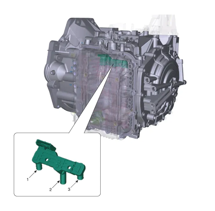
| 1. Input speed sensor 2. Output speed sensor |
3. Middle speed sensor |
Schematic diagrams
| Circuit Diagram |

Repair procedures
| Inspection |
|

| Removal |
|

| 1. |
Turn ignition switch OFF and disconnect the negative (-) battery cable.
|
| 2. |
Remove the battery and battery tray.
(Refer to Engine Electrical System - "Battery")
|
| 3. |
Remove the air duct and air cleaner assembly.
(Refer to Engine Mechanical System - "Air Cleaner")
|
| 4. |
Remove the under cover.
(Refer to Engine Mechanical System - "Engine Room Under Cover")
|
| 5. |
Drain the coolant.(If equipped ATF warmer)
(Refer to Engine Mechanical System - "Coolant")
|
| 6. |
Loosen the drain plug (A) and reinstall the drain plug after draining
ATF totally.
|


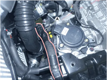
| 7. |
Loosen the fixing bolt (A) and then removing the bracket.
|
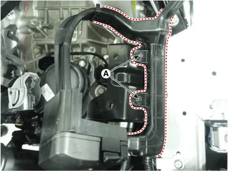
| 8. |
Loosen the fixing bolts (A) and then removing the bracket.
|
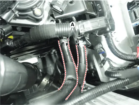
| 9. |
Separate the ATF cooler hose (A).
|

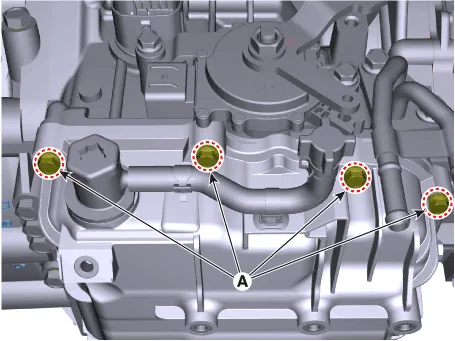
| 10. |
Loosen the upper bolts (A) of the valve body cover.
|
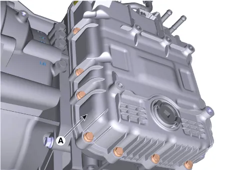
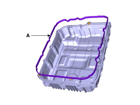
| 11. |
Remove the valve body cover (A) after removing the bolts.
|


| 12. |
Loosen the bolts and then Separate the main harness (A).
|
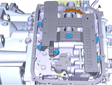
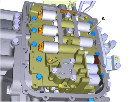
| 13. |
Remove the valve body assembly (A).
|

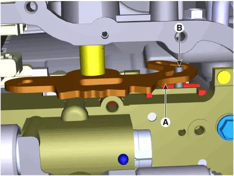
| 14. |
Disconnect the speed sensor connector (A).
|

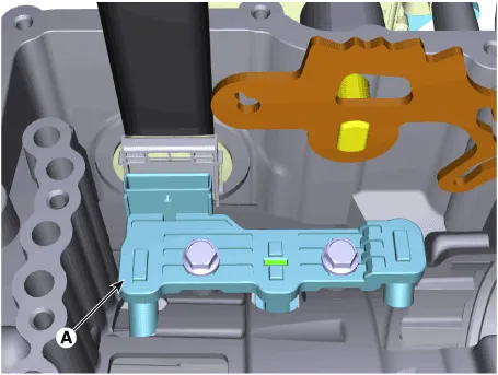
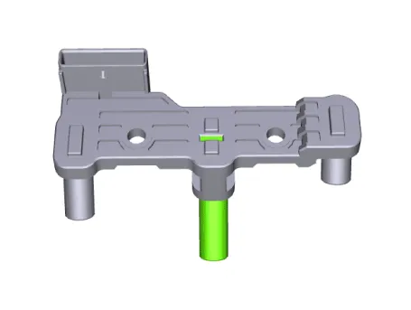
| 15. |
Loosen the bolts and then removing the speed sensor (A).
|
| Installation |
| 1. |
To install, reverse the removal procedure.
|
| 2. |
Inject the automatic transaxle oil and inspect the oil level.
(Refer to Automatic Transaxle System - "Automatic Transaxle Fluid")
|

Specifications Specification ▷ Type: Negative Thermal Coefficient Type Temp [(°C)°F] Resistance (kΩ) (-40) -40 48.
Specifications Specification Item Specification Power supply (V) 4.5 - 5.5V Output type Shifting range Non-contact (2 channel PWM signal) Description and operation Description Output position signal(P,R,N,D) by the actuator operation to the controller (SBW Control Unit_SCU).
Other information:
Hyundai Palisade (LX2) 2020-2026 Service Manual: Rear Heater Core
Repair procedures Replacement 1. Remove the rear heater & A/C unit. (Refer to Rear Heater - "Rear Heater Unit") 2. Loosen the mounting screws and remove the rear heater core cover (A).
Hyundai Palisade (LX2) 2020-2026 Service Manual: Ultrasonic Sensor
Schematic diagrams Schematic Diagrams Repair procedures Removal 1. Remove the bumper cover. (Refer to Body - "Front Bumper Cover") (Refer to Body - "Rear Bumper Cover") 2.
Categories
- Manuals Home
- Hyundai Palisade Owners Manual
- Hyundai Palisade Service Manual
- Lift and Support Points
- Repair procedures
- Electrochromatic Mirror (ECM) with homelink system
- New on site
- Most important about car
