Hyundai Palisade (LX2): Automatic Transaxle Control System / Position Sensor
Specifications
| Specification |
|
Item |
Specification |
|
|
Power supply (V) |
4.5 - 5.5V |
|
|
Output type |
Shifting range |
Non-contact (2 channel PWM signal) |
Description and operation
| Description |
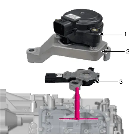
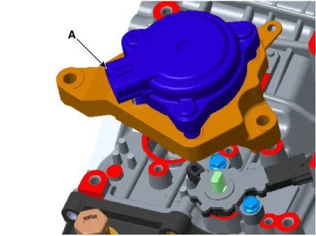
| 1. Electric shift actuator
2. Bracket 3. Position sensors |
Troubleshooting
| Troubleshooting |
|
Major Symptom |
Expected Cause |
Items to Check and Measures |
|
Shock when shifting to and from D/R Motor run-up when shifting to and from D/R |
Faulty position sensor "N" setting |
Use the "N" setting jig and adjust the "N" setting. (Refer to "Automatic Transaxle System – Position Sensor") |
|
Faulty oil pressure in the valve body |
Replace valve body assembly or inspect/replace transaxle assembly |
|
|
Faulty engine start Current gear not indicated in the Cluster Warning Lamp ON Engine stall while stopped Creeping not possible Auto parking release disabled |
Faulty CAN terminating resistance/circuit |
Check TCM/battery management system module. |
|
Check TCM wiring connector connection. |
||
|
Faulty position sensor circuit fuse |
Check fuse and junction box terminal, and repair. |
|
|
Faulty position sensor wiring connector |
Check for foreign substance in the wiring connector, and check for gap on
the terminal. |
|
|
Check sealing on unused pin, and check for corrosion on the terminal. |
||
|
Faulty reverse lamp circuit |
Check reverse lamp ground, and reassemble if necessary. |
|
|
Faulty position sensor wiring ground |
Check wiring ground, and reassemble if necessary. |
|
|
Position sensor faulty code |
Inspect in accordance with the inspection flow, then replace position sensor
if necessary. |
Repair procedures
| Removal |
|

| 1. |
Turn ignition switch OFF and disconnect the negative (-) battery cable.
|
| 2. |
Remove the battery and battery tray.
(Refer to Engine Electrical System - "Battery")
|
| 3. |
Remove the air duct and the air cleaner assembly.
(Refer to Engine Mechanical System - "Air Cleaner")
|
| 4. |
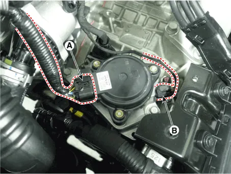
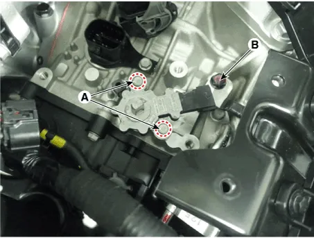
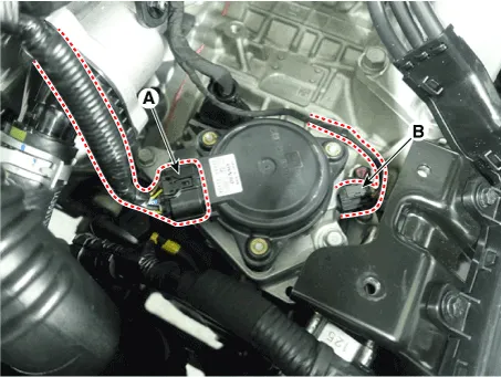
Disconnect the position sensor connector (A).
|
| 5. |
Disconnect the electronic shift actuator connector (B).
|
| 6. |
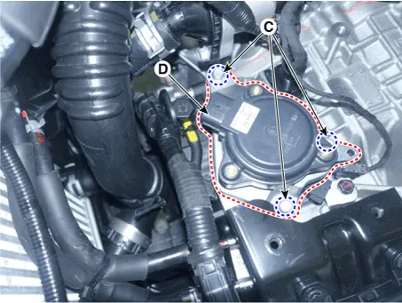
Remove the electronic shift actuator (D) after removing the bolts (C).
|
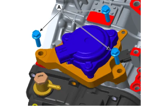
| 7. |
Remove the position sensor (B) after removing the bolts (A).
|
| Installation |
| 1. |
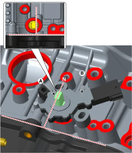
Check that the shaft (A) is in the "N" position.
|
| 2. |
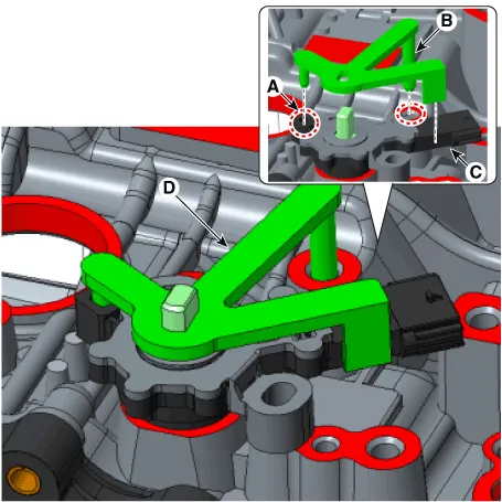
Install the position sensor (B).
|
| 3. |
Install the position sensor "N" fixing SST(No.:09459 - 4G100)(D) in
the sensor (A), case pin (B) and anti-rotation guide (C).
|
| 4. |
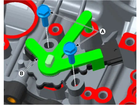
Install the bolts (A) in the position sensor.
|
| 5. |
Remove the position sensor "N" fixing SST(No.:09459 - 4G100)(B).
|
| 6. |
Install the electric shift actuator (A).
|
| 7. |
Install the bolts (A).
|
| 8. |
Connect the electric shift actuator (A) and position sensor (B).
|
| 9. |
Install the air duct and the air cleaner assembly.
(Refer to Engine Mechanical System - "Air Cleaner")
|
| 10. |
Install the battery and battery tray.
(Refer to Engine Electrical System - "Battery")
|
| 11. |
Check that operating surely at each range of the position sensor corresponding
to each position of electric shift button.
|
Specifications Specification ▷Type : Hall effect sensor Item Specification Operating condition (°C)°F (-40 to 150) -40 to 302 Output voltage (V) High 1.
Repair procedures Removal 1. Turn ignition switch OFF and disconnect the negative (-) battery cable. 2.
Other information:
Hyundai Palisade (LX2) 2020-2026 Service Manual: Front View Camera Unit
Schematic diagrams Circuit Diagram Repair procedures Removal 1. Disconnect the negative (-) battery terminal. 2. Remove the inside rear view mirror cover (A) and rain sensor cover (B).
Hyundai Palisade (LX2) 2020-2026 Service Manual: Schematic diagrams
System Block Diagram Component Parts And Function Outline Component part Function Vehicle-speed sensor, ESP/ABS Control Module Converts vehicle speed to pulse. ECM Receives signals from sensor and control switches.
Categories
- Manuals Home
- Hyundai Palisade Owners Manual
- Hyundai Palisade Service Manual
- Engine Mechanical System
- Maintenance
- Electronic Child Safety Lock System
- New on site
- Most important about car
