Hyundai Palisade (LX2): Seat Electrical / Power Seat Motor
Repair procedures
| Inspection |
| 1. |
Disconnect the connectors for each motor.
(Refer to Body - "Front Seat Assembly")
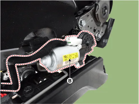
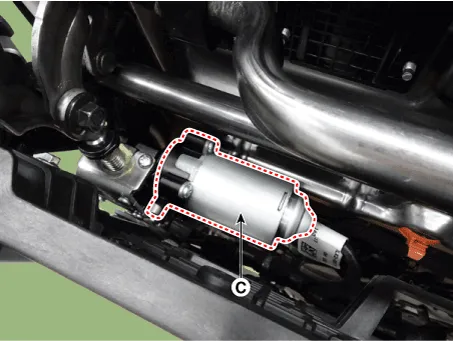
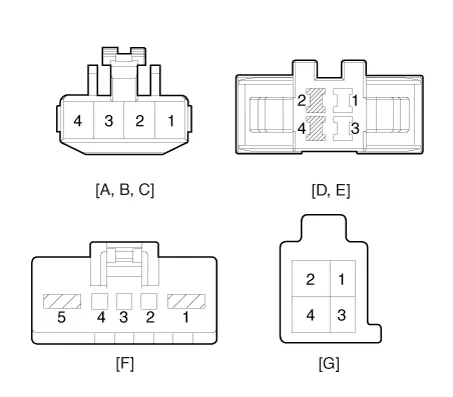
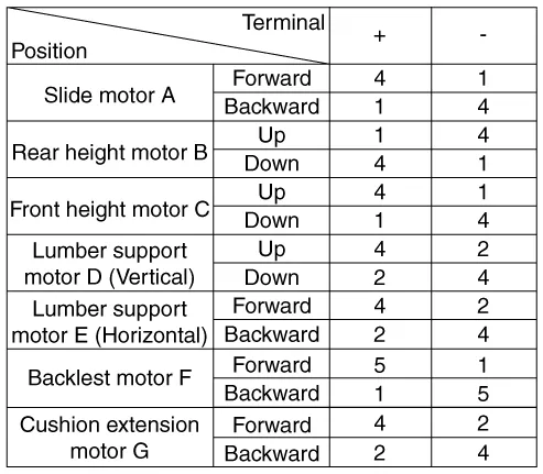
A : Slide motor
B : Rear height motor
C : Front height motor
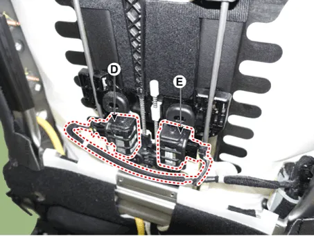
D : Lumber support motor (Vertical)
E : Lumber support motor (Horizontal)
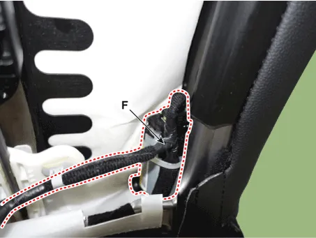
F : Backlest motor
G : Cushion extension motor
|

| 2. |
With the battery connected directly to the motor terminals, check if
the motors run smoothly.
|
| 3. |
Reverse the connections and check that the motor turns in reverse.
|
| 4. |
If there is an abnormality, replace the motors.
|
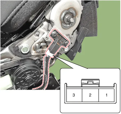
| 1. |
Disconnect the limit switch and operate the limit switch.
|
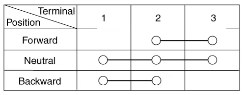
| 2. |
Check for continuity between the terminals.
|
| 3. |
Make sure that the seat operation is normal in the reverse after the
maximum operation.
|
| 4. |
If there is an abnormality, replace the limit switch.
|
Component Location 1. Backlest motor 2. Front height motor 3. Cushion extension motor 4. Lumber support motor 5.
Repair procedures Removal 1. Disconnect the negative (-) battery terminal. 2. Remove the front seat shield outer cover.
Other information:
Hyundai Palisade (LX2) 2020-2026 Service Manual: Blower Motor
Repair procedures Inspection 1. Connect the battery voltage and check the blower motor rotation. 2. If the blower motor does not operate well, substitute with a known-good blower motor and check for proper operation.
Hyundai Palisade (LX2) 2020-2026 Service Manual: Smart Cruise Control (SCC) Switch
Components and components location Components 1. Remote control switch (Audio swtich) 2. Remote control switch (Cruise control switch) Schematic diagrams Circuit Diagram Trip + SCC Repair procedures Removal 1.
Categories
- Manuals Home
- Hyundai Palisade Owners Manual
- Hyundai Palisade Service Manual
- How to reset the power liftgate
- Body Electrical System
- Automatic Transaxle Fluid (ATF)
- New on site
- Most important about car
