Hyundai Palisade (LX2): Lighting System / Overhead Console Lamp
Hyundai Palisade (LX2) 2020-2026 Service Manual / Body Electrical System / Lighting System / Overhead Console Lamp
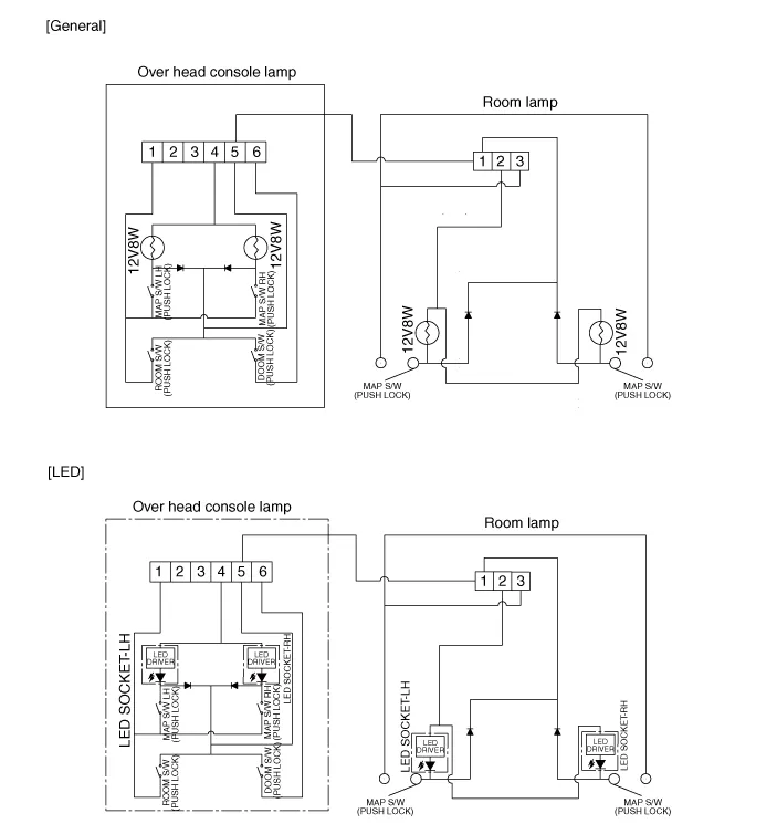
Schematic diagrams
| Circuit Diagram |
Repair procedures
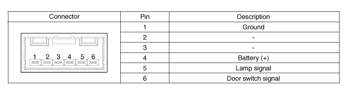
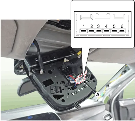
| Inspection |
| 1. |
Remove the overhead console lamp connector (A) then check for continuity
between terminals. If the continuity is not as specified, replace the
map lamp switch.
|
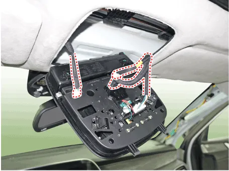
| Removal |
| 1. |
Disconnect the negative (-) battery terminal.
|
| 2. |
Remove the mounting screws (2EA).
And then remove the overhead console.
|

| 3. |
Remove the overhead console after disconnect the connector.
|
| Installation |
| 1. |
Install the overhead console lamp after connecting the connector.
|
| 2. |
Install the lens after tightening 2 screws.
|
Repair procedures Removal Room lamp 1. Disconnect the negative (-) battery terminal. 2. Detach the lamp lens (A) from the room lamp with a flat-tip screwdriver.
Repair procedures Removal 1. Disconnct the negative (-) battery terminal. 2. Remove the audio/AVN keyboard assembly.
Other information:
Hyundai Palisade (LX2) 2020-2026 Service Manual: Auto Defogging Sensor
Description and operation Description The auto defogging sensor is installed on the front window glass. The sensor judges and sends signal if moisture occurs to blow out wind for defogging. The air conditioner control module receives signal from the sensor and restrains moisture and eliminate defog by controlling the intak
Hyundai Palisade (LX2) 2020-2026 Service Manual: Specifications
Categories
- Manuals Home
- Hyundai Palisade Owners Manual
- Hyundai Palisade Service Manual
- Rain Sensor
- Scheduled maintenance services
- General Tightening Torque Table
- New on site
- Most important about car

Copyright © 2026 www.hpalisadelx.com - 0.0227