
Hyundai Palisade (LX2): Rear Bumper / Rear Bumper Cover
Components and components location
| Component Location |
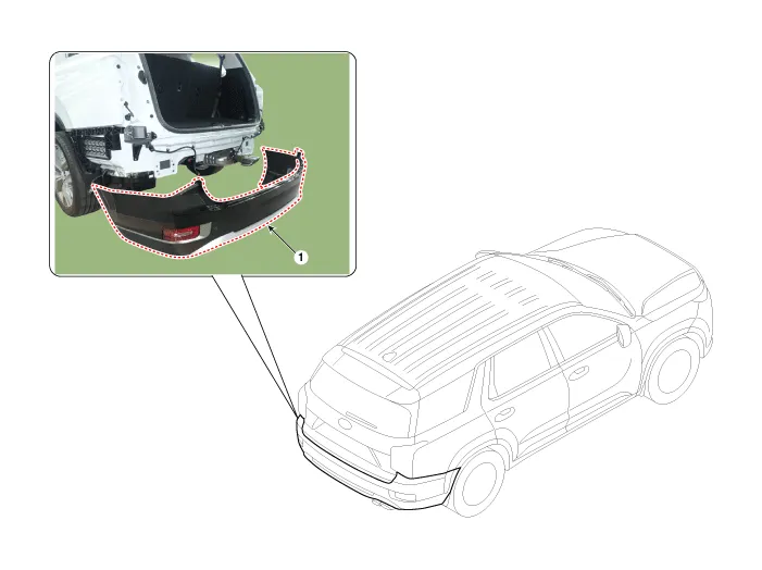
| 1. Rear bumper cover |
Repair procedures
| Replacement |
|

|

| 1. |
Using a flat-tip screwdriver or remover and remove the rear combination
lamp cover (A).
|

| 2. |
Remove the rear combination lamp (A) and separate the connector (B).
|

| 3. |
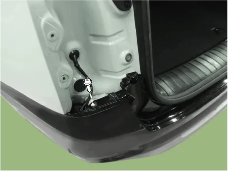
Loosen the rear bumper mounting clips.
|
| 4. |
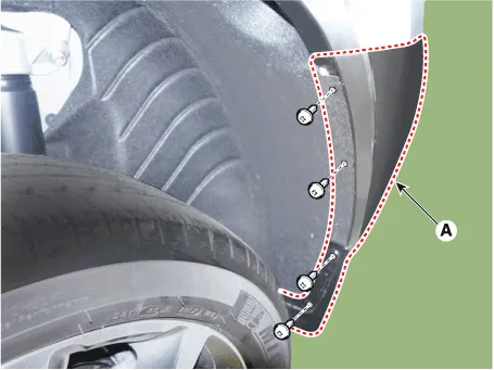
Loosen the mounting screws and retainer on the side of rear bumper (A),
detach the side part of rear bumper.
|

| 5. |
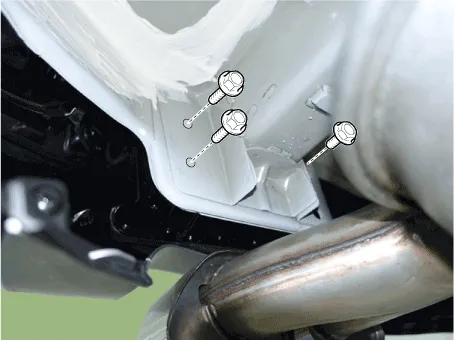
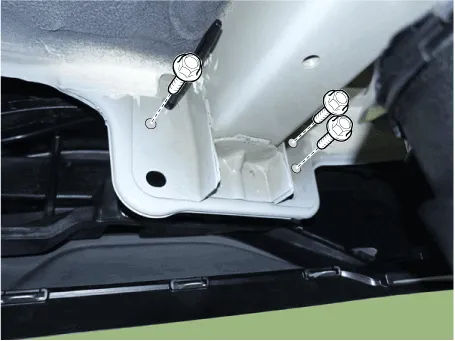
Loosen the rear bumper mounting bolts.
[RH]
[LH]
|
| 6. |
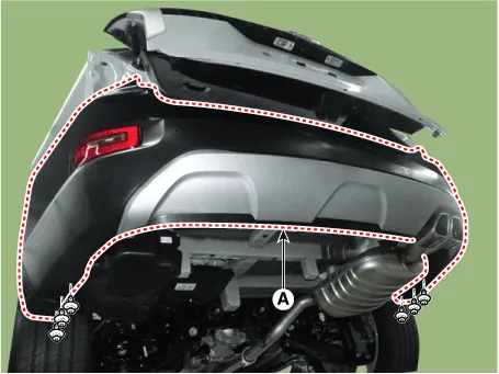
Loosen the mounting clips and remove the rear bumper cover (A).
|
| 7. |
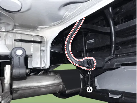
Press the lock pin and separate the BSD Connector (A).
|

| 8. |
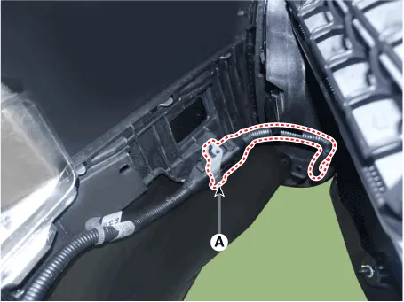
Press the lock pin and separate the rear bumper main connector (A).
|
| 9. |
To install, reverse removal procedure.
|

Components 1. Rear bumper cover 2. Rear side under cover 3. Rear bumper side braket
Components and components location Component Location 1. Rear bumper beam assembly
Other information:
Hyundai Palisade (LX2) 2020-2026 Service Manual: Rear Heater Unit
Components and components location Component Location 1. Rear Heater & A/C Unit Repair procedures Replacement • Be careful not to damage the parts located under the vehicle
Hyundai Palisade (LX2) 2020-2026 Service Manual: Cruise Control (CC) Switch
Components and components location Components 1. Remote control switch (Audio swtich) 2. Remote control switch (Cruise control switch) Schematic diagrams Circuit Diagram Repair procedures Removal 1.
Categories
- Manuals Home
- Hyundai Palisade Owners Manual
- Hyundai Palisade Service Manual
- Rain Sensor
- Resetting the Driver's Seat Memory System
- Engine Control/Fuel System
- New on site
- Most important about car
