Hyundai Palisade (LX2): Automatic Transaxle Control System / Electric Shift Button
Repair procedures
| Removal |
| 1. |
Turn ignition switch OFF and disconnect the negative (-) battery cable.
|
| 2. |
Remove the console upper cover.
(Refer to Body - "Floor Console Assembly")
|
| 3. |
Remove the electric shift button (A).
|
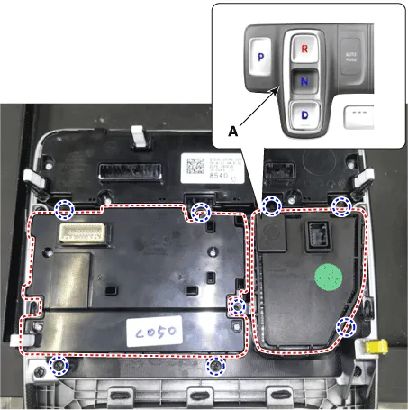
| 4. |
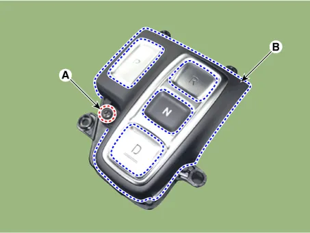
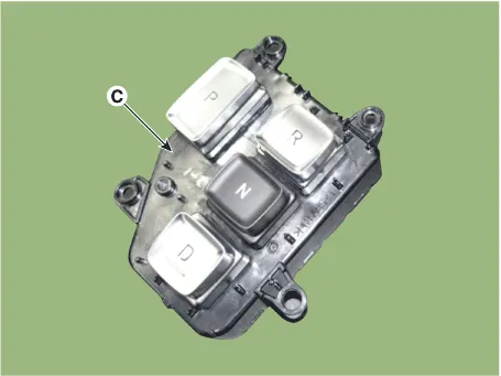
Loosen the screw (A) and then disconnect the upper cover (B) with the
shift button module (C)
|
| Installation |
| 1. |
To install, reverse the removal procedure.
|
Specifications Specification Item Specification Power supply (V) 4.5 - 5.5V Output type Shifting range Non-contact (2 channel PWM signal) Description and operation Description Output position signal(P,R,N,D) by the actuator operation to the controller (SBW Control Unit_SCU).
Components and components location Component Location 1. SBW Control Unit (SCU) Repair procedures Removal 1.
Other information:
Hyundai Palisade (LX2) 2020-2026 Service Manual: Specifications
Hyundai Palisade (LX2) 2020-2026 Service Manual: Ultrasonic Sensor
Schematic diagrams Schematic Diagrams Repair procedures Removal 1. Remove the bumper cover. (Refer to Body - "Front Bumper Cover") (Refer to Body - "Rear Bumper Cover") 2.
Categories
- Manuals Home
- Hyundai Palisade Owners Manual
- Hyundai Palisade Service Manual
- Repair procedures
- Body (Interior and Exterior)
- Automatic Transaxle Fluid (ATF)
- New on site
- Most important about car
