Hyundai Palisade (LX2): Crash Pad / Center Fascia Panel
Components and components location
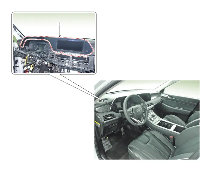
1. Front center fascia panel
|
|
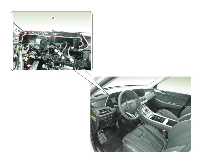
2. Rear center fascia panel
|
|
Repair procedures
[Front center facsia panel]
| • |
When removing with a flat-tip screwdriver or remover, wrap protective
tape around the tools to prevent damage to components.
|
| • |
Put on gloves to prevent hand injuries.
|
|
| • |
Use a plastic panel removal tool to remove interior trim pieces
without marring the surface.
|
| • |
Take care not to bend or scratch the trim and panels.
|
|
| 1. |
Remove the crash pad center garnish.
(Refer to Crash pad - "Crash pad garnish")
|
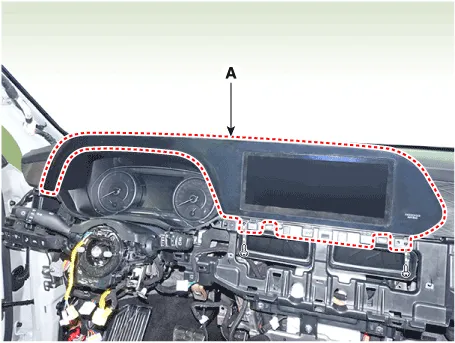
| 2. |
Loosen the mounting screws and remove the front center fascia panel
(A).
|
| 3. |
Press the lock pin and separate the passenger airbag connector.
|
| 4. |
To install, reverse removal procedure.
|
| • |
Replace any damaged clips (or pin-type retainers).
|
|
[Rear center facsia panel]
| • |
When removing with a flat-tip screwdriver or remover, wrap protective
tape around the tools to prevent damage to components.
|
| • |
Put on gloves to prevent hand injuries.
|
|
| • |
Use a plastic panel removal tool to remove interior trim pieces
without marring the surface.
|
| • |
Take care not to bend or scratch the trim and panels.
|
|
| 1. |
Remove the cluster fascia panel.
(Refer to Crash pad - "Cluster fascia panel")
|
| 2. |
Remove the AVN head unit.
(Refer to Body Electrical System - "AVN head unit")
|
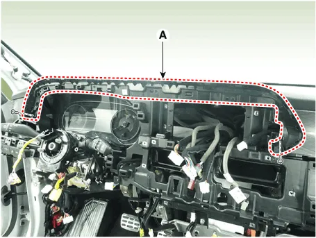
| 3. |
Loosen the mounting screws and remove the rear center fascia panel (A).
|
| 4. |
To install, reverse removal procedure.
|
| • |
Replace any damaged clips (or pin-type retainers).
|
|
Components and components location
Component Location
1. Cluster fascia panel
Repair procedures
Replacement
•
When removing with a flat-tip screwdriver or remover, wrap protective
tape around the tools to prevent damage to components.
Components and components location
Component Location
1. Crash pad center garnish
3. Crash pad garnish [LH]
2.
Other information:
Components and components location
Component Location
1. Heater unit assembly
Components
1. Heater core assembly
2. Heater unit pad
3. Heater lower cover
4. Drain hose
5.
Repair procedures
Removal
1.
Disconnect the negative (-) battery terminal.
2.
Remove the floor console upper cover.
(Refer to Body - "Floor Console Assembly")
3.


