Hyundai Palisade (LX2): SRSCM / Front Impact Sensor (FIS)
Components and components location

1. Front impact sensor (FIS)
|
2. Front impact sensor (FIS)
|
Description and operation
The front impact sensor (FIS) is installed in the Front End Module (FEM). They
are remote sensors that detect acceleration due to a collision at its mounting
location. The primary purpose of the Front Impact Sensor (FIS) is to provide
an indication of a collision. The Front Impact Sensor (FIS) sends acceleration
data to the SRSCM.
Repair procedures
| • |
Do not turn the ignition switch ON and do not connect the battery
cable while replacing the front impact sensor.
|
|
| 1. |
Disconnect the battery negative cable, and wait for at least three minutes
before beginning work.
|
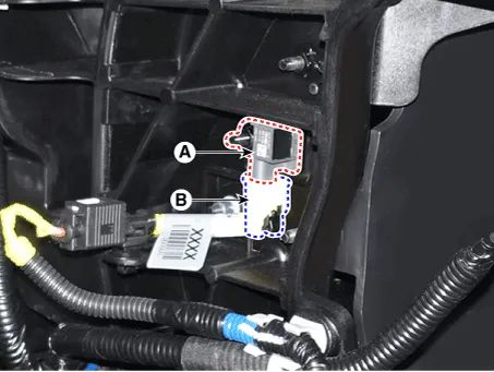
| 2. |
Disconnect the front impact sensor connector (B) and then remove the
front impact sensor (A) after loosening the mounting bolt.
|
| • |
Do not turn the ignition switch ON and do not connect the battery
cable while replacing the front impact sensor.
|
|
| 1. |
Install a new front impact sensor.
|
| 2. |
Tighten the front impact sensor mounting nut.
|
Tightening torque :
7.8 - 10.8 N.m (0.8 - 1.0 kgf.m, 5.7 - 7.2 lb-ft)
|
|
| 3. |
Connect the front impact sensor connector.
|
| 4. |
Install the radiator assembly.
|
| 5. |
Reconnect the battery negative cable.
|
| 6. |
After installing the front impact sensor, confirm proper system operation
:
Turn the ignition switch ON; the SRS indicator light should turn on
for about six seconds and then go off.
|
Components and components location
Components
[LH]
1. Supplemental Restraint System
Control Module (SRSCM)
Description and operation
Description
The primary purpose of the SRSCM (Supplemental Restraints System Control Module)
is to discriminate between an event that warrants restraint system deployment
and an event that does not.
Components and components location
Components
1. Gravity Side Impact Sensor
[G-SIS (B-Pillar)]
2. Gravity Side Impact Sensor [G-SIS (C-Pillar)]
3.
Other information:
Components and components location
Component Location
1. Rear Heater & A/C Unit
Repair procedures
Replacement
•
Be careful not to damage the parts located under the vehicle
Description
The cruise control system is engaged by the cruise "ON/OFF" main switch located
on right of steering wheel column. The system has the capability to cruise,
coast, accelerate and resume speed.
It also has a safety interrupt, engaged upon depressing brake or shifting select
lever.


