Hyundai Palisade (LX2): Evaporative Emission Control System / Canister
Repair procedures
| Removal |
| 1. |
Switch "OFF" the ignition and disconnect the negative (-) battery terminal.
|
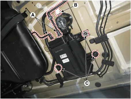
| 2. |
Disconnect the vent hose quick-connector (B), the vapor hose quick-connector
(A) from the canister.
|
| 3. |
Remove the fuel tank air filter assembly after removing the mounting
bolts (C).
|
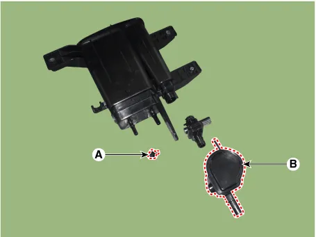
| 4. |
Remove the fuel tank air filter mounting bolt (A).
|
| 5. |
Remove the clip, and then separate the fuel tank air filter (B) from
the canister after rotating it in the direction of the arrow in the
figure.
|
| Inspection |
| 1. |
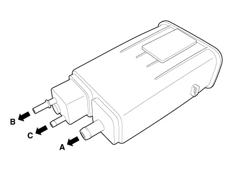
Check for the following items visually.
A : Canister ‚ÜĒ Atmosphere
B : Canister ‚ÜĒ Fuel Tank (Fuel Pump)
C : Canister ‚ÜĒ Intake Manifold
|
| Installation |
| 1. |
Install in the reverse order of removal.
|
Schematic Diagram 1. Air cleaner 2. Delivery pipe & injector 3. Engine 4. Purge control solenoid valve (PCSV) 5.
Specifications Specification Item Specification Coil Resistance (‚Ą¶) 18.5 - 22.
Other information:
Hyundai Palisade (LX2) 2020-2026 Service Manual: In-car Sensor
Description and operation Description The In-car air temperature sensor is built in the heater & A/C control unit. The sensor consists of a thermistor that measures the inside temperature. The signal decided by the resistance value that changes in accordance with perceived inside temperature, is delivered to heater co
Hyundai Palisade (LX2) 2020-2026 Service Manual: Components and components location
Categories
- Manuals Home
- Hyundai Palisade Owners Manual
- Hyundai Palisade Service Manual
- Electrochromatic Mirror (ECM) with homelink system
- Automatic Transaxle Fluid (ATF)
- Cylinder Head
- New on site
- Most important about car

Copyright © 2026 www.hpalisadelx.com - 0.017