Hyundai Palisade (LX2): Rear Corner Radar System / Warning Indicator
Components and components location
| Components |
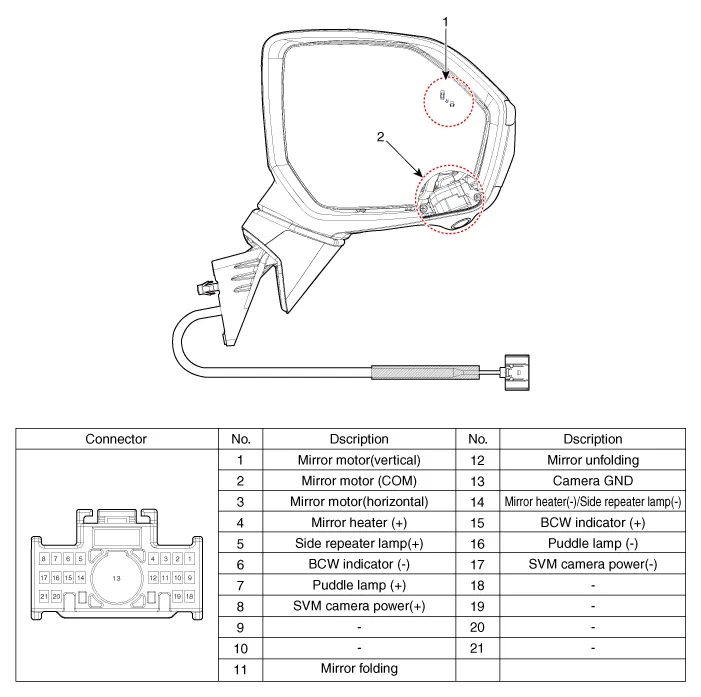
| 1. Warning indicator |
2. SVM camera |
Repair procedures
| Removal |
| 1. |
Disconnect the negative (-) battery terminal.
|
| 2. |
Remove the front door trim.
(Refer to Body - "Front door trim")
|
| 3. |
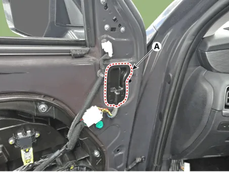
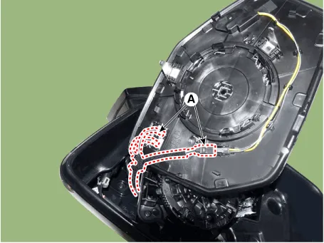
Remove the outside rear view cover (A).
|
| 4. |
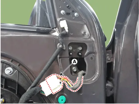
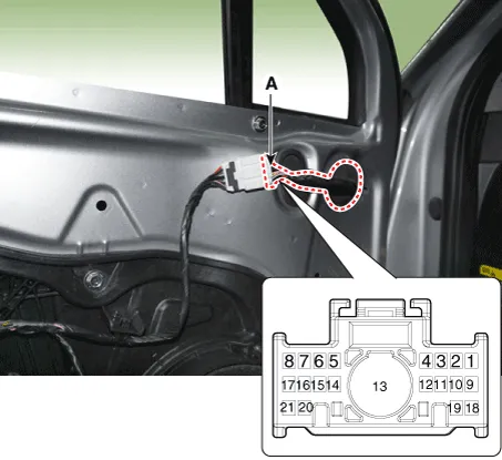
Disconnect the mirror connector (A).
|
| 5. |
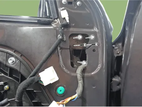
Loosen the mounting nut and then remove the outside rear view mirror.
|
| 6. |
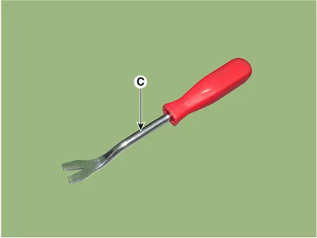
Using a fastener remover (C), remove the mirror (A) as illustration
below.
|


| 7. |
Disconnect heat wire connectors (A) and then remove the mirror.
|
| Installation |
| 1. |
Install the outside mirror.
|
| 2. |
Connect the negative (-) battery terminal.
|
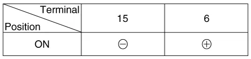
| Inspection |
| 1. |
Disconnect the power door mirror connector from the harness
|
Components and components location Circuit Diagram Repair procedures Inspection 1. Disconnect the negative (-) battery terminal.
Other information:
Hyundai Palisade (LX2) 2020-2026 Service Manual: Wireless Power Charging Unit
Components and positions Components Circuit diagram Circuit Diagram Repair procedures Removal Handling wireless charging system parts by wet hands may cause electric shock.
Hyundai Palisade (LX2) 2020-2026 Service Manual: Rear Blower Motor
Repair procedures Replacement 1. Disconnect the negative (-) battery terminal. 2. Remove the luggage side trim (Refer to Body - "Luggage Side Trim ") 3. Separate the rear blower motor connector (A), loosen the mounting screws and remov
Categories
- Manuals Home
- Hyundai Palisade Owners Manual
- Hyundai Palisade Service Manual
- Body Electrical System
- General Tightening Torque Table
- Resetting the Driver's Seat Memory System
- New on site
- Most important about car
