Hyundai Palisade: Cruise Control System (CC) / Troubleshooting

Hyundai Palisade (LX2) 2020-2024 Service Manual / Advanced Driver Assistance System (ADAS) / Cruise Control System (CC) / Troubleshooting

Trouble Symptom Charts
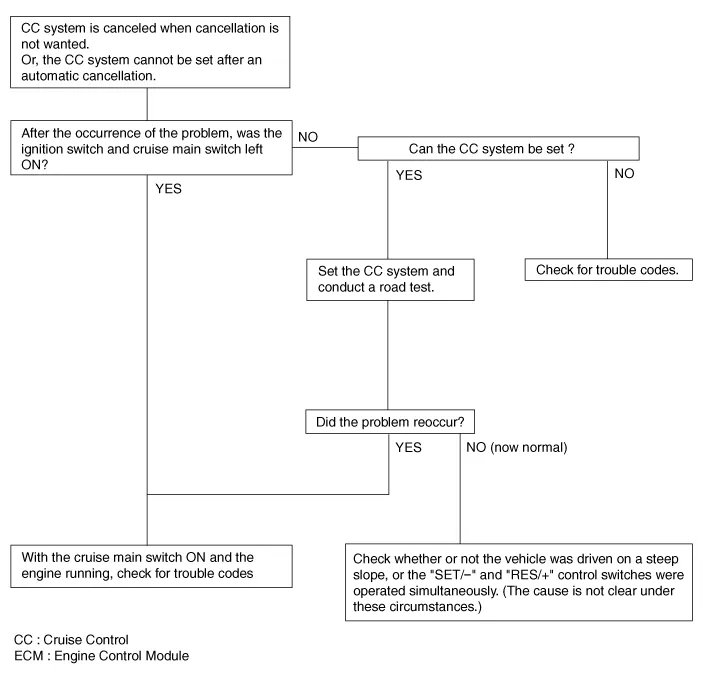
Trouble Symptom 1

Hyundai Palisade. Troubleshooting

Trouble Symptom 2
Trouble symptom
Probable cause
Remedy
The set vehicle speed varies greatly upward or downward
"Surging" (repeated alternating acceleration and deceleration) occurs after setting
Malfunction of the vehicle speed sensor circuit
Repair the vehicle speed sensor system, or replace the part
Malfunction of ECM
Check input and output signals at ECM

Trouble Symptom 3
Trouble symptom
Probable cause
Remedy
The CC system is not canceled when the brake pedal is depressed
Damaged or disconnected wiring of the brake pedal switch
Repair the harness or replace the brake pedal switch
Malfunction of the ECM signals
Check input and output signals at ECM

Trouble Symptom 4
Trouble symptom
Probable cause
Remedy
The CC system is not canceled when the shift lever is moved to the "N" position (It is canceled, however, when the brake pedal is depressed)
Damaged or disconnected wiring of inhibitor switch input circuit
Repair the harness or repair or replace the inhibitor switch
Improper adjustment of inhibitor switch
Malfunction of the ECM signals
Check input and output signals at ECM

Trouble Symptom 5
Trouble symptom
Probable cause
Remedy
Cannot decelerate (coast) by using the "SET/–" switch
Temporary damaged or disconnected wiring of "SET/–" switch input circuit
Repair the harness or replace the "SET/–" switch
Malfunction of the ECM signals
Check input and output signals at ECM

Trouble Symptom 6
Trouble symptom
Probable cause
Remedy
Cannot accelerate or resume speed by using the "RES/+" switch
Damaged or disconnected wiring, or short circuit, or "RES/+" switch input circuit
Repair the harness or replace the "RES/+" switch
Malfunction of the ECM signals
Check input and output signals at ECM

Trouble Symptom 7
Trouble symptom
Probable cause
Remedy
CC system can be set while driving at a vehicle speed of less than 40km/h (25mph), or there is no automatic cancellation at that speed
Malfunction of the vehicle-speed sensor circuit
Repair the vehicle speed sensor system, or replace the part
Malfunction of the ECM signals
Check input and output signals at ECM

Trouble Symptom 8
Trouble symptom
Probable cause
Remedy
The cruise main switch indicator lamp does not illuminate (But CC system is normal)
Damaged or disconnected bulb of cruise main switch indicator lamp
Repair the harness or replace the part.
Harness damaged or disconnected

    Schematic diagrams

    System Block Diagram Component Parts And Function Outline Component part Function Vehicle-speed sensor, ESP/ABS Control Module Converts vehicle speed to pulse...

    Cruise Control (CC) Switch

    Components and components location Components 1. Remote control switch (Audio swtich) 2. Remote control switch (Cruise control switch) Schematic diagrams Circuit Diagram Repair procedures Removal 1...

    Other information:

    Hyundai Palisade (LX2) 2020-2024 Owner's Manual: Heated Steering Wheel


    When the ignition switch is in the ON position or when the engine is running, press the heated steering wheel button to warm the steering wheel. The indicator on the button will illuminate. To turn the heated steering wheel off, press the button again...

    Hyundai Palisade (LX2) 2020-2024 Service Manual: Engine Control Module (ECM)


    Schematic diagrams ECM Terminal and Input / Output Signal ECM Terminal Function Connector [A] Pin No Description Connected to 1 Ignition Coil (Cylinder #4) control output Ignition Coil (Cylinder #4) 2 Injector (Cylinder #3) [High] control output Injector (Cylinder #3) 3 Injector (Cylinder #5) [High] control output Injector (Cylinder #5) 4 Injector (Cylinder #1) [High] control output Injector (Cylinder #1) 5 Camshaft Position Sensor (CMPS) [Bank 2 / Exhaust] signal input Camshaft Position Sensor (CMPS) [Bank 2 / Exhaust] 6 Camshaft Position Sensor (CMPS) [Bank 2 / Intake] signal input Camshaft Position Sensor (CMPS) [Bank 2 / Intake] 7 Throttle Position Sensor (TPS) 2 signal input Throttle Position Sensor (TPS) 2 8 -   9 Rail Pressure Sensor (RPS) signal input Rail Pressure Sensor (RPS) 10 CVVT Oil Temperature Sensor (OTS) signal input CVVT Oil Temperature Sensor (OTS) 11 -   12 -   13 Sensor power (+5V) CVVT Oil Temperature Sensor (OTS) Manifold Absolute Pressure Sensor (MAPS) 14 -   15 -   16 -   17 -   18 -   19 ETC Motor [-] control output ETC Motor 20 Heated Oxygen Sensor (HO2S) [Bank 1 / Sensor 1] Heater control output Heated Oxygen Sensor (HO2S) [Bank 1 / Sensor 1] 21 Heated Oxygen Sensor (HO2S) [Bank 2 / Sensor 1] Heater control output Heated Oxygen Sensor (HO2S) [Bank 2 / Sensor 1] 22 Ignition Coil (Cylinder #5) control output Ignition Coil (Cylinder #5 23 Injector (Cylinder #6) [High] control output Injector (Cylinder #6) 24 Injector (Cylinder #2) [High] control output Injector (Cylinder #2) 25 Injector (Cylinder #4) [High] control output Injector (Cylinder #4) 26 Camshaft Position Sensor (CMPS) [Bank 1 / Exhaust] signal input Camshaft Position Sensor (CMPS) [Bank 1 / Exhaust] 27 Camshaft Position Sensor (CMPS) [Bank 1 / Intake] signal input Camshaft Position Sensor (CMPS) [Bank 1 / Intake] 28 Intake Air Temperature Sensor (IATS) signal input Intake Air Temperature Sensor (IATS) 29 Manifold Absolute Pressure Sensor (MAPS) signal input Manifold Absolute Pressure Sensor (MAPS) 30 -   31 -   32 -   33 -   34 Sensor power (+5V) Camshaft Position Sensor (CMPS) [Bank 1 / Exhaust] Camshaft Position Sensor (CMPS) [Bank 2 / Intake] 35 -   36 Sensor power (+5V) Camshaft Position Sensor (CMPS) [Bank 1 / Intake] Camshaft Position Sensor (CMPS) [Bank 2 / Exhaust] 37 -   38 Purge Control Solenoid Valve (PCSV) control output Purge Control Solenoid Valve (PCSV) 39 -   40 ETC Motor [+] control output ETC Motor 41 -   42 -   43 Ignition Coil (Cylinder #1) control output Ignition Coil (Cylinder #1) 44 Injector (Cylinder #6) [Low] control output Injector (Cylinder #6) 45 Injector (Cylinder #3) [Low] control output Injector (Cylinder #3) 46 Injector (Cylinder #2) [Low] control output Injector (Cylinder #2) 47 Sensor ground Camshaft Position Sensor (CMPS) [Bank 1 / Exhaust] Camshaft Position Sensor (CMPS) [Bank 2 / Intake] 48 Sensor ground Manifold Absolute Pressure Sensor (MAPS) Oil Pressure Sensor (OPS) 49 Sensor ground Camshaft Position Sensor (CMPS) [Bank 1 / Intake] Camshaft Position Sensor (CMPS) [Bank 2 / Exhaust] 50 -   51 -   52 -   53 -   54 Engine Coolant Temperature Sensor (ECTS) signal input Engine Coolant Temperature Sensor (ECTS) 55 Sensor Shield Crankshaft Position Sensor (CKPS) Knock Sensor (KS) #1 [Bank 1] Knock Sensor (KS) #2 [Bank 2] 56 Sensor power (+5V) Rail Pressure Sensor (RPS) 57 -   58 Sensor ground Engine Coolant Temperature Sensor (ECTS) Rail Pressure Sensor (RPS) 59 Sensor ground Throttle Position Sensor (TPS) 1 Throttle Position Sensor (TPS) 2 60 Variable Intake Solenoid (VIS) Valve 1 control output Variable Intake Solenoid (VIS) Valve 1 61 Variable Intake Solenoid (VIS) Valve 2 control output Variable Intake Solenoid (VIS) Valve 2 62 -   63 -   64 Ignition Coil (Cylinder #2) control output Ignition Coil (Cylinder #2) 65 Injector (Cylinder #1) [Low] control output Injector (Cylinder #1) 66 Injector (Cylinder #4) [Low] control output Injector (Cylinder #4) 67 Injector (Cylinder #5) [Low] control output Injector (Cylinder #5) 68 Crankshaft Position Sensor (CKPS) [High] signal input Crankshaft Position Sensor (CKPS) 69 Crankshaft Position Sensor (CKPS) [Low] signal input Crankshaft Position Sensor (CKPS) 70 -   71 -   72 Oil pressure switch signal input Oil Pressure Sensor (OPS) 73 -   74 -   75 Throttle Position Sensor (TPS) 1 signal input Throttle Position Sensor (TPS) 1 76 Knock Sensor (KS) [Bank 1] [Low] signal input Knock Sensor (KS) [Bank 1] 77 Knock Sensor (KS) [Bank 2] [Low] signal input Knock Sensor (KS) [Bank 2] 78 Sensor ground Heated Oxygen Sensor (HO2S) [Bank 2 / Sensor 2] 79 Rc/Rp (Pump Cell Voltage) Heated Oxygen Sensor (HO2S) [Bank 2 / Sensor 1] 80 VS+ (NERNST Cell Voltage) Heated Oxygen Sensor (HO2S) [Bank 2 / Sensor 1] 81 Heated Oxygen Sensor (HO2S) [Bank 2 / Sensor 2] signal input Heated Oxygen Sensor (HO2S) [Bank 2 / Sensor 2] 82 VS+ (NERNST Cell Voltage) Heated Oxygen Sensor (HO2S) [Bank 1 / Sensor 1] 83 Rc (Compensative Resistance) Heated Oxygen Sensor (HO2S) [Bank 1 / Sensor 1] 84 Oil Pressure Solenoid Valve control output Oil Pressure Solenoid Valve 85 Ignition Coil (Cylinder #6) control output Ignition Coil (Cylinder #6) 86 Ignition Coil (Cylinder #3) control output Ignition Coil (Cylinder #3) 87 Fuel Pressure Control Valve (FPCV) [High] control output Fuel Pressure Control Valve (FPCV) 88 Fuel Pressure Control Valve (FPCV) [Low] control output Fuel Pressure Control Valve (FPCV) 89 Heated Oxygen Sensor (HO2S) [Bank 2 / Sensor 2] Heater control output Heated Oxygen Sensor (HO2S) [Bank 2 / Sensor 2] 90 Heated Oxygen Sensor (HO2S) [Bank 1 / Sensor 2] Heater control output Heated Oxygen Sensor (HO2S) [Bank 1 / Sensor 2] 91 CVVT Oil Control Valve (OCV) [Bank 2 / Exhaust] control output CVVT Oil Control Valve (OCV) [Bank 2 / Exhaust] 92 CVVT Oil Control Valve (OCV) [Bank 1 / Exhaust] control output CVVT Oil Control Valve (OCV) [Bank 1 / Exhaust] 93 Variable Force Solenoid (VFS) [Bank 2 / Intake] control output Variable Force Solenoid (VFS) [Bank 2 / Intake] 94 Variable Force Solenoid (VFS) [Bank 1 / Intake] control output Variable Force Solenoid (VFS) [Bank 1 / Intake] 95 -   96 Sensor power (+5V) Throttle Position Sensor (TPS) 1 Throttle Position Sensor (TPS) 2 97 Knock Sensor (KS) [Bank 1] [High] signal input Knock Sensor (KS) [Bank 1] 98 Knock Sensor (KS) [Bank 2] [High] signal input Knock Sensor (KS) [Bank 2] 99 Sensor ground Heated Oxygen Sensor (HO2S) [Bank 1 / Sensor 2] 100 -   101 Rc (Compensative Resistance) Heated Oxygen Sensor (HO2S) [Bank 2 / Sensor 1] 102 VS-/IP- (Common ground) Heated Oxygen Sensor (HO2S) [Bank 2 / Sensor 1] 103 Heated Oxygen Sensor (HO2S) [Bank 1 / Sensor 2] signal input Heated Oxygen Sensor (HO2S) [Bank 1 / Sensor 2] 104 VS-/IP- (Common ground) Heated Oxygen Sensor (HO2S) [Bank 1 / Sensor 1] 105 Rc/Rp (Pump Cell Voltage) Heated Oxygen Sensor (HO2S) [Bank 1 / Sensor 1] Connector [K] Pin No Description Connected to 1 ECM ground Chassis ground 2 ECM ground Chassis ground 3 Battery power (B+) Main Relay 4 ECM ground Chassis ground 5 Battery power (B+) Main Relay 6 Battery power (B+) Main Relay 7 -   8 -   9 -   10 -   11 -   12 -   13 Sensor ground A/C Pressure Transducer (APT) 14 Immobilizer communication line Immobilizer Control Module 15 Fuel Level Sender (FLS) signal input [Fuel pump] Fuel Level Sender (FLS) 16 -   17 -   18 -   19 -   20 Sensor power (+5V) Accelerator Position Sensor (APS) 1 21 Main Relay control output Main Relay 22 -   23 -   24 -   25 -   26 -   27 -   28 Accelerator Position Sensor (APS) 2 signal input Accelerator Position Sensor (APS) 2 29 -   30 -   31 -   32 Fuel Level Sender (FLS) signal input [Sub Fuel Sender] Sub Fuel Level Sender 33 Fuel Pump Relay control output Fuel Pump Relay 34 -   35 Sensor power (+5V) A/C Pressure Transducer (APT) 36 Sensor power (+5V) Accelerator Position Sensor (APS) 2 37 -   38 Vehicle speed signal input VDC control module 39 -   40 -   41 Start signal input Start Relay 42 -   43 -   44 -   45 -   46 -   47 Sensor ground Accelerator Position Sensor (APS) 2 48 -   49 Brake Switch [Test] signal input Brake Switch 50 -   51 -   52 Sensor ground Accelerator Position Sensor (APS) 1 53 -   54 -   55 -   56 -   57 -   58 -   59 -   60 P-CAN [Low] Other control module, Data Link Connector (DLC), Multi-Purpose Check Connector 61 -   62 -   63 -   64 A/C Pressure Transducer (APT) signal input A/C Pressure Transducer (APT) 65 -   66 -   67 -   68 -   69 LIN (Local Interconnect Network) Serial Bus Line Battery Sensor 70 -   71 Cooling Fan Relay control output Cooling Fan Relay 72 Engine speed signal output Integrated Body Control Unit (IBU) 73 -   74 -   75 -   76 -   77 P-CAN [High] Other control module, Data Link Connector (DLC), Multi-Purpose Check Connector 78 -   79 Start Relay control output Start Relay 80 -   81 -   82 Accelerator Position Sensor (APS) 1 signal input Accelerator Position Sensor (APS) 1 83 Brake Switch [Light] signal input Brake Switch 84 -   85 -   86 -   87 -   88 -   89 -   90 -   91 -   ECM Terminal Input/ Output signal Connector [A] Pin No  Description Condition Type Level 1 Ignition Coil (Cylinder #4) control output Idle Pulse Vpeak = 400V Frequency : 0 - 58...

    Categories

    Air Bag Warning Labels

    Hyundai Palisade. Air Bag Warning Labels

    Air bag warning labels, required by the U.S. National Highway Traffic Safety Administration (NHTSA), are attached to alert the driver and passengers of potential risks of the air bag system. Be sure to read all of the information about the air bags that are installed on your vehicle in this Owners Manual.

    read more


    Copyright © 2024 www.hpalisadelx.com