
Hyundai Palisade (LX2): Heater / Evaporator Core
Repair procedures
| Replacement |
| 1. |
Disconnect the negative (-) battery terminal.
|
| 2. |
Remove the heater and blower assembly.
(Refer to Heater - "Heater Unit")
|
| 3. |
Remove the heater core.
(Refer to Heater - "Heater Core")
|
| 4. |
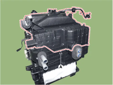
Loosen the mounting screws and remove the evaporator core cover (A).
|
| 5. |
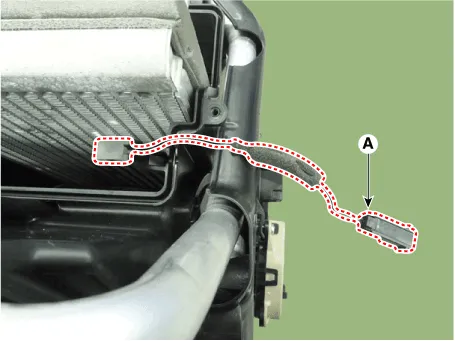
Separate the evaporator temperature sensor (A) from the evaporator core.
|
| 6. |
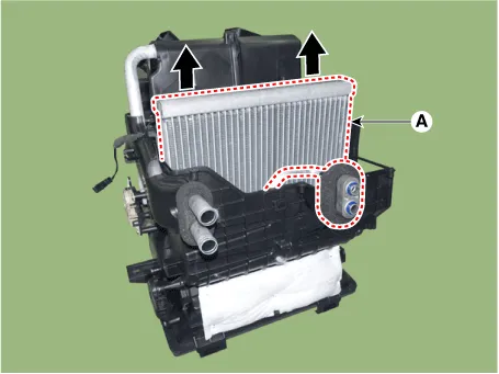
Remove the evaporator core (A) from the heater unit.
|
| 7. |
Install in the reverse order of removal.
|


Repair procedures Replacement 1. Disconnect the negative (-) battery terminal. 2. Remove the heater and blower assembly.
Description and operation Description The PTC (Positive Temperature Coefficient) heater is installed at the exit or the backside of the heater core.
Other information:
Hyundai Palisade (LX2) 2020-2026 Service Manual: General safety information and caution
General Safety Information and Caution 1. Be careful when driving the vehicle using the smart cruise control system as follows. (1) On curves or inclines/declines • The smart cruise control system may have limits to detect
Hyundai Palisade (LX2) 2020-2026 Service Manual: Troubleshooting
Diagnosis with Diagnostic tool 1. In the body electrical system, failure can be quickly diagnosed by using the vehicle diagnostic system (Diagnostic tool). The diagnostic system (Diagnostic tool) provides the following information.
Categories
- Manuals Home
- Hyundai Palisade Owners Manual
- Hyundai Palisade Service Manual
- How to reset the power liftgate
- Rear Heater Unit
- Rain Sensor
- New on site
- Most important about car
