Hyundai Palisade (LX2): Cruise Control System (CC) / Cruise Control (CC) Switch
Components and components location
| Components |
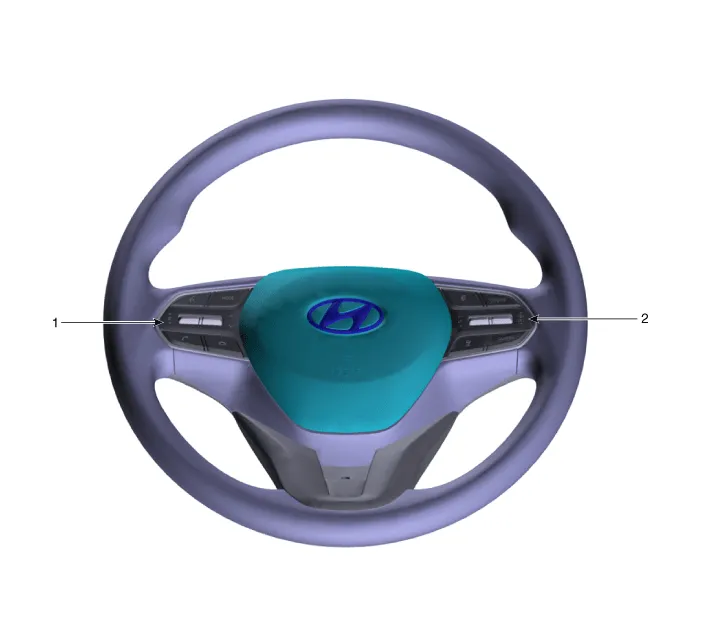
| 1. Remote control switch (Audio
swtich) |
2. Remote control switch (Cruise
control switch) |
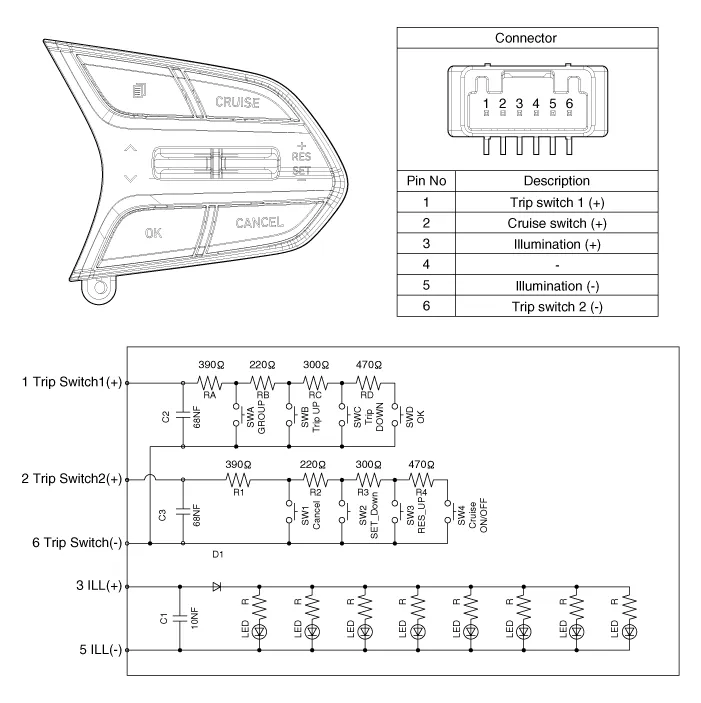
Schematic diagrams
| Circuit Diagram |
Repair procedures
| Removal |
| 1. |
Disconnect the negative (-) battery terminal.
|
| 2. |
Remove the driver airbag module.
(Refer to Restraint - "Driver Airbag (DAB) Module and Clock Spring")
|
| 3. |
Remove the steering wheel.
(Refer to Steering System - "Steering Column and Shaft")
|
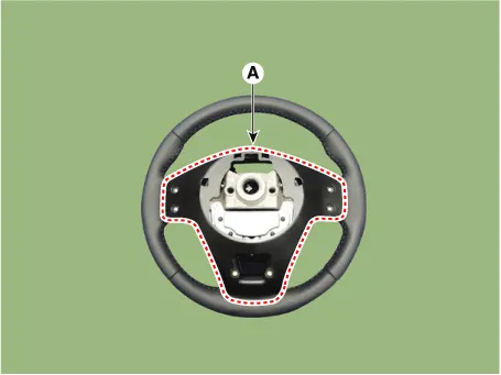
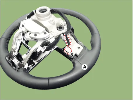
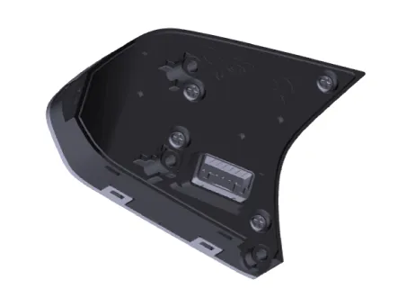
| 4. |
Remove the steering back cover (A) after loosening the screws.
|
| 5. |
Disconnect the remote control switch connector (A).
|
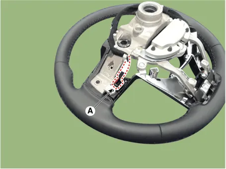
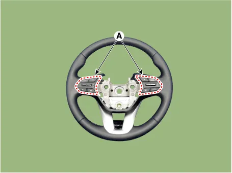
| 6. |
Remove the remote control switchs (A) after loosening the screws.
|
| Installation |
| 1. |
Install in the reverse order of removal.
|
| Inspection |
| 1. |
Disconnect the cruise control switch connector from the control switch.
|
| 2. |
Measure resistance between terminals on the control switch when each
function switch is ON. (switch is depressed)
|
| 3. |
If not within specification, replace switch.
|
Trouble Symptom Charts Trouble Symptom 1 Trouble Symptom 2 Trouble symptom Probable cause Remedy The set vehicle speed varies greatly upward or downward "Surging" (repeated alternating acceleration and deceleration) occurs after setting Malfunction of the vehicle speed sensor circuit Repair the vehicle speed sensor system, or replace the part Malfunction of ECM Check input and output signals at ECM Trouble Symptom 3 Trouble symptom Probable cause Remedy The CC system is not canceled when the brake pedal is depressed Damaged or disconnected wiring of the brake pedal switch Repair the harness or replace the brake pedal switch Malfunction of the ECM signals Check input and output signals at ECM Trouble Symptom 4 Trouble symptom Probable cause Remedy The CC system is not canceled when the shift lever is moved to the "N" position (It is canceled, however, when the brake pedal is depressed) Damaged or disconnected wiring of inhibitor switch input circuit Repair the harness or repair or replace the inhibitor switch Improper adjustment of inhibitor switch Malfunction of the ECM signals Check input and output signals at ECM Trouble Symptom 5 Trouble symptom Probable cause Remedy Cannot decelerate (coast) by using the "SET/–" switch Temporary damaged or disconnected wiring of "SET/–" switch input circuit Repair the harness or replace the "SET/–" switch Malfunction of the ECM signals Check input and output signals at ECM Trouble Symptom 6 Trouble symptom Probable cause Remedy Cannot accelerate or resume speed by using the "RES/+" switch Damaged or disconnected wiring, or short circuit, or "RES/+" switch input circuit Repair the harness or replace the "RES/+" switch Malfunction of the ECM signals Check input and output signals at ECM Trouble Symptom 7 Trouble symptom Probable cause Remedy CC system can be set while driving at a vehicle speed of less than 40km/h (25mph), or there is no automatic cancellation at that speed Malfunction of the vehicle-speed sensor circuit Repair the vehicle speed sensor system, or replace the part Malfunction of the ECM signals Check input and output signals at ECM Trouble Symptom 8 Trouble symptom Probable cause Remedy The cruise main switch indicator lamp does not illuminate (But CC system is normal) Damaged or disconnected bulb of cruise main switch indicator lamp Repair the harness or replace the part.
Other information:
Hyundai Palisade (LX2) 2020-2026 Service Manual: Compressor oil
Repair procedures Oil Specification 1. The R-134a or R-1234yf system requires synthetic (PAG) compressor oil whereas the R-12 system requires mineral compressor oil. The two oils must never be mixed. 2.
Hyundai Palisade (LX2) 2020-2026 Service Manual: Description and operation
Description • PDW consists of 8 sensors (front : 4 units, rear : 4 units) that are used to detect obstacles and transmit the result in three separate warning levels, the first, second and third to IBU via LIN communication.
Categories
- Manuals Home
- Hyundai Palisade Owners Manual
- Hyundai Palisade Service Manual
- General Tightening Torque Table
- Maintenance
- Emergency liftgate safety release
- New on site
- Most important about car
