Hyundai Palisade (LX2): Timing System / Timing Chain Cover
Repair procedures
| Removal |
|

|

|

|

| 1. |
Remove the engine cover.
(Refer to Engine And Transaxle Assembly - "Engine Cover")
|
| 2. |
Remove the engine room under cover.
(Refer to Engine And Transaxle Assembly - "Engine Room Under Cover")
|
| 3. |
Drain the engine coolant.
(Refer to Cooling System - "Coolant")
|
| 4. |
Drain the engine oil.
(Refer to Lubrication System - "Engine Oil")
|
| 5. |
Remove the air cleaner assembly.
(Refer to Intake And Exhaust System - "Air Cleaner")
|
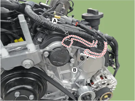
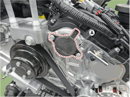
| 6. |
Disconnect the variable force solenoid (VFS) valve connector (A) and
ground cable (B).
|
| 7. |
Remove the surge tank.
(Refer to Intake And Exhaust System - "Surge Tank")
|
| 8. |
Remove the LH / RH cylinder head cover.
(Refer to Cylinder Head Assembly - "Cylinder Head Cover")
|
| 9. |
Remove the drive belt.
(Refer to Timing System - "Drive Belt")
|
| 10. |
Remove the idler.
(Refer to Timing System - "Idler")
|
| 11. |
Remove the drive belt tensioner.
(Refer to Timing System - "Drive Belt Tensioner")
|
| 12. |
Remove the crankshaft damper pulley.
(Refer to Timing System - "Crankshaft Damper Pulley")
|
| 13. |
Remove the water pump.
(Refer to Cooling System - "Water Pump")
|
| 14. |
Remove the lower oil pan.
(Refer to Lubrication System - "Oil Pan")
|
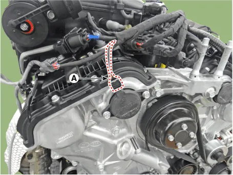
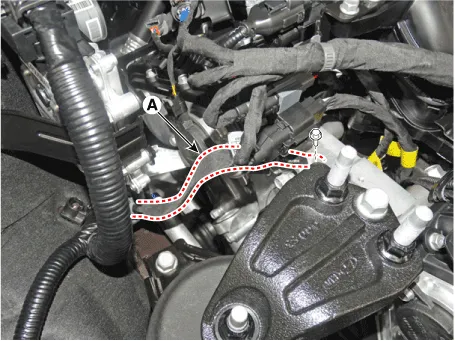
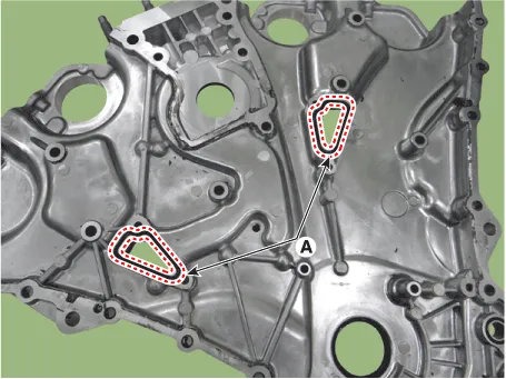
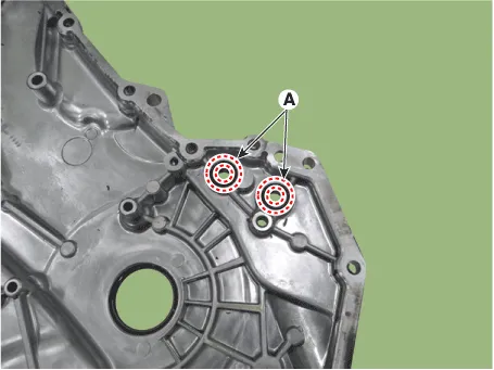
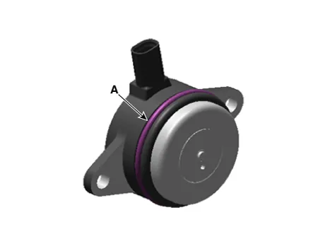
| 15. |
Remove the RH and LH variable force solenoid (VFS) valve (A).
[RH]
[LH]
|


| 16. |
Remove the engine mounting support bracket.
|

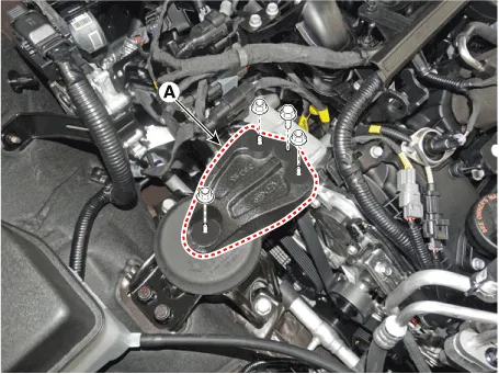
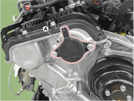
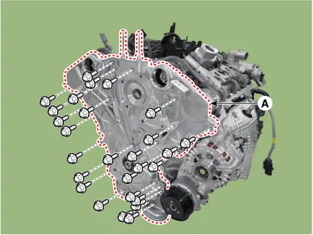
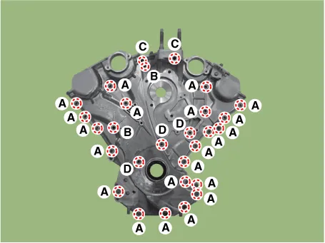
| 17. |
Remove the timing chain cover (A).
|

| Installation |
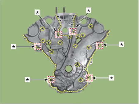
| 1. |
Install the timing chain cover.
|


| 2. |
Install the engine mounting support bracket.
|


| 3. |
Install the RH and LH variable force solenoid (VFS) valve (A).
[RH]
[LH]
|


| 4. |
Install the remaining parts in the reverse order of removal.
|

Repair procedures Removal • Be careful not to damage the parts located under the vehicle (floor under cover, fuel filter, fuel tank and canister) when raising the vehicle using the lift.
Repair procedures Removal • Be careful not to damage the parts located under the vehicle (floor under cover, fuel filter, fuel tank and canister) when raising the vehicle using the lift.
Other information:
Hyundai Palisade (LX2) 2020-2026 Service Manual: Climate Control Air Filter
Description and operation Description The climate control air filter is located in the blower unit. It eliminates foreign materials and odor. The particle filter performs a role as an odor filter as well as a conventional dust filter to ensure comfortable interior environment.
Hyundai Palisade (LX2) 2020-2026 Service Manual: Troubleshooting
Troubleshooting 1) After replacing H/UNIT, always check that the system operates properly. 2) If the failure persists after replacing the H/UNIT, do not replace the unit.
Categories
- Manuals Home
- Hyundai Palisade Owners Manual
- Hyundai Palisade Service Manual
- Resetting the Driver's Seat Memory System
- Body Electrical System
- Engine Mechanical System
- New on site
- Most important about car
