Hyundai Palisade (LX2): Heater / Temperature Control Actuator
Description and operation
| Description |
Components and components location
| Component Location |
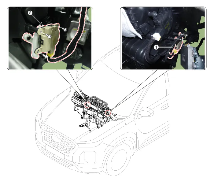
| 1. Temperature control actuator
[LH] |
2. Temperature control actuator
[RH] |
Repair procedures
| Inspection |
| 1. |
Turn the ignition switch OFF.
|
| 2. |
Disconnect the temperature control actuator connector.
|
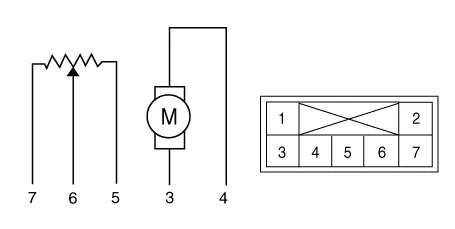
| 3. |
Verify that the temperature control actuator operates to the cool position
when connecting 12V to terminal 3 and grounding terminal 4.
Verify that the temperature control actuator operates to the warm position
when connected in reverse.
[Driver]
[Passenger]
|
| 4. |
Connect the temperature control actuator connector.
|
| 5. |
Turn the ignition switch ON.
|
| 6. |
Check the voltage between terminal 5 and 6.
Specification
It will feedback the current position of the actuator to controls.
|
| 7. |
If the measured voltage is not within specification, substitute with
a known-good temperature control actuator and check for proper operation.
|
| 8. |
Replace the temperature control actuator if it is proved that there
is a problem with it.
|
| Replacement |
| 1. |
Disconnect the negative (-) battery terminal.
|
| 2. |
Remove the crash pad lower panel.
(Refer to Body - "Crash Pad Lower Panel")
|
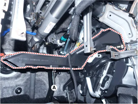
| 3. |
Loosen the mounting screws and remove the shower duct [LH] (A).
|
| 4. |
Separate the Surround view monitoring (SVM) unit.
(Refer to Body Electrical System - "SVM Unit")
|
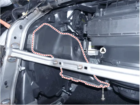
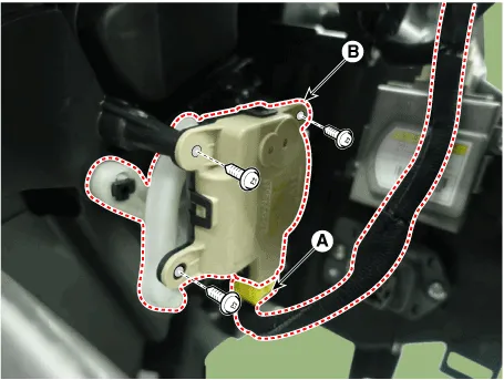
| 5. |
Separate the temperature control actuator connector (A) and loosen the
mounting screw and remove the temperature control actuator (B).
|

| 6. |
Install in the reverse order of removal.
|
| 1. |
Disconnect the negative (-) battery terminal.
|
| 2. |
Remove the crash pad center panel.
(Refer to Body - "Crash Pad Center Panel")
|
| 3. |
Loosen the mounting screws and remove the shower duct [RH] (A).
|
| 4. |
Separate the temperature control actuator connector (A) and loosen the
mounting screw and remove the temperature control actuator (B).
|
| 5. |
Install in the reverse order of removal.
|
Description and operation Description The PTC (Positive Temperature Coefficient) heater is installed at the exit or the backside of the heater core.
Description and operation Description The mode control actuator is located at the heater unit. It adjusts the position of the mode door by operating the mode control actuator based on the signal of the A/C control unit.
Other information:
Hyundai Palisade (LX2) 2020-2026 Service Manual: Auto Defogging Sensor
Description and operation Description The auto defogging sensor is installed on the front window glass. The sensor judges and sends signal if moisture occurs to blow out wind for defogging. The air conditioner control module receives signal from the sensor and restrains moisture and eliminate defog by controlling the intak
Hyundai Palisade (LX2) 2020-2026 Service Manual: Description and operation
Description Blind-Spot Radar is a system that measures the relative speed and distance from the following vehicles by using two electromagnetic wave radar sensors attached to the rear bumper, and detects any vehicle within the blind spot zone and gives off alarm (visual and auditory).
Categories
- Manuals Home
- Hyundai Palisade Owners Manual
- Hyundai Palisade Service Manual
- Rain Sensor
- Automatic Transaxle System (A8LF1)
- Lift and Support Points
- New on site
- Most important about car
