Hyundai Palisade (LX2): Engine Electrical System / Specifications
| Specification |
| Ignition Coil |
|
Item |
Specification |
|
Rated Voltage (V) |
12 |
|
Operating Voltage (V) |
5 - 16 |
| Spark plug |
|
Item |
Specification |
|
Type |
SILZKR7E11 |
|
Gap |
1.0 - 1.1 mm (0.0394 - 0.0433 in.) |
|
Insulation resistance (MΩ) |
10 or more |
| Condenser |
|
Item |
Specification |
|
Capacitance (uF) |
0.47 [1KHz] |
|
Insulation resistance (MΩ) |
1,000 [DC 500 V/1 Min] |
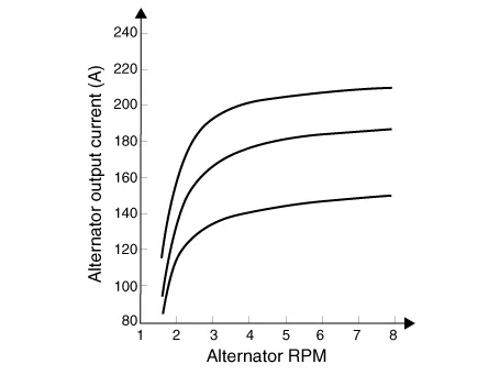
| Alternator |
|
Item |
Specification |
|
Rated voltage |
13.5V , 180A |
|
Speed in use |
1,500 - 18,000rpm |
|
Voltage regulator |
IC Regulator built in type |
|
Default regulated voltage (V) [COM terminal] |
14.09 - 14.91 (-35°C) |
|
13.96 - 15.04 (140°C) |
|
|
Pin |
1 |
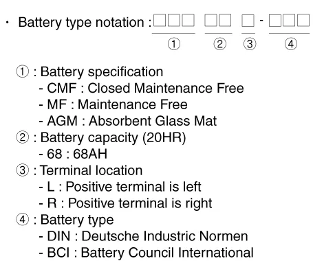
| Battery |
|
Item |
Specification |
|
Model type |
AGM80L-BCI |
|
Capacity [20HR/5HR] (AH) |
80 / 64 |
|
Cold Cranking Amperage (A) |
800 (SAE) / 640 (EN) |
|
Reserve Capacity (Min) |
155 |
| â–·CMF68L-DIN |
|
Item |
Specification |
|
Capacity [20HR / 5HR] (AH) |
68 / 54 |
|
Cold Cranking Amperage (A) |
600 (SAE / EN) |
|
Reserve Capacity (Min) |
113 |
| â–·CMF80L-DIN |
|
Item |
Specification |
|
Capacity [20HR / 5HR] (AH) |
80 / 64 |
|
Cold Cranking Amperage (A) |
660 (SAE / EN) |
|
Reserve Capacity (Min) |
145 |
| â–·CMF90L-DIN |
|
Item |
Specification |
|
Capacity [20HR / 5HR] (AH) |
90 / 72 |
|
Cold Cranking Amperage (A) |
740 (SAE) / 740 (EN) |
|
Reserve Capacity (Min) |
170 |
| â–·CMF68L-DIN [Openable] |
|
Item |
Specification |
|
Capacity [20HR / 5HR] (AH) |
68 / 54 |
|
Cold Cranking Amperage (A) |
600 (SAE / EN) |
|
Reserve Capacity (Min) |
113 |
| â–·CMF80L-DIN [Openable] |
|
Item |
Specification |
|
Capacity [20HR / 5HR] (AH) |
80 / 64 |
|
Cold Cranking Amperage (A) |
660 (SAE / EN) |
|
Reserve Capacity (Min) |
145 |
| â–·CMF90L-DIN [Openable] |
|
Item |
Specification |
|
Capacity [20HR / 5HR] (AH) |
90 / 72 |
|
Cold Cranking Amperage (A) |
740 (SAE) / 740 (EN) |
|
Reserve Capacity (Min) |
170 |
|

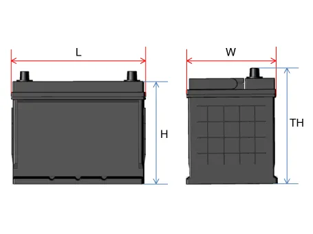
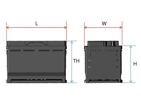
BCI Type
DIN Type
AGM DIN Type
|

| Starter |
|
Item |
Specification |
|
|
Rated voltage |
12 V, 1.7 kW |
|
|
The number of pinion teeth |
11 |
|
|
Performance [No-load, 11.5 V] |
Ampere |
Max. 105 A |
|
Speed |
Min. 2,800 rpm |
|
Special Service Tools Tool Name / Number Illustration Description Alternator pulley remover wrench 09373-27000 Removal and installation of alternator pulley
Other information:
Hyundai Palisade (LX2) 2020-2026 Service Manual: Wireless Power Charging Unit
Components and positions Components Circuit diagram Circuit Diagram Repair procedures Removal Handling wireless charging system parts by wet hands may cause electric shock.
Hyundai Palisade (LX2) 2020-2026 Service Manual: Intake Actuator
Description and operation Description The intake actuator is located at the blower unit. It regulates the intake door by a signal from the control unit. Pressing the intake selection switch will shift between recirculation and fresh air modes.
Categories
- Manuals Home
- Hyundai Palisade Owners Manual
- Hyundai Palisade Service Manual
- General Tightening Torque Table
- Maintenance
- Body (Interior and Exterior)
- New on site
- Most important about car
