Hyundai Palisade (LX2): Immobilizer System / Immobilizer Control Unit
Repair procedures
| Removal |
| 1. |
Disconnect the negative (-) battery terminal.
|
| 2. |
Remove the glove box housing.
(Refer to Body - "Glove Box Housing Cover")
|
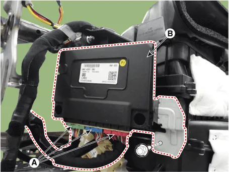
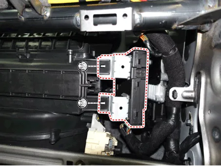
| 3. |
Disconnect the connector (A) and then remove the IBU (B) after loosening
mounting nuts.
|
| Installation |
| 1. |
Install the IBU after connecting the unit connector.
|
| 2. |
Install the glove box housing.
|
| 3. |
Connect the negative (-) battery terminal.
|
Diagnosis with Diagnostic tool 1. In the body electrical system, failure can be quickly diagnosed by using the vehicle diagnostic system (Diagnostic tool).
Repair procedures Removal 1. Disconnect the negative (-) battery terminal. 2. Remove the crash pad lower panel.
Other information:
Hyundai Palisade (LX2) 2020-2026 Service Manual: Components and components location
Component Location 1. Start Stop Button(SSB) 2. FOB key 3. Tailgate open switch 4. Interior antenna 1 5. Interior antenna 2 6. Intergrated Body Control Unit (IBU) 7. Trunk antenna 8. Door handle & door antenna 9.
Hyundai Palisade (LX2) 2020-2026 Service Manual: Heater Unit
Components and components location Component Location 1. Heater unit assembly Components 1. Heater core assembly 2. Heater unit pad 3. Heater lower cover 4. Drain hose 5.
Categories
- Manuals Home
- Hyundai Palisade Owners Manual
- Hyundai Palisade Service Manual
- Electrochromatic Mirror (ECM) with homelink system
- Rear Heater Unit
- Lift and Support Points
- New on site
- Most important about car
