Hyundai Palisade (LX2): Rear Suspension System / Rear Stabilizer Bar
Repair procedures
| Removal |
| 1. |
Raise the vehicle, and make sure it is securely supported.
|
| 2. |
In the case of 4WD vehicle, remove the rear differential assembly.
(Refer to Driveshaft and axle - "Rear Differential Carrier")
|
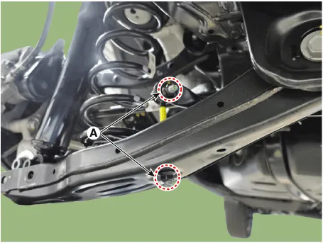
| 3. |
Loosen the nut (A) and then remove the stabilizer link.
|
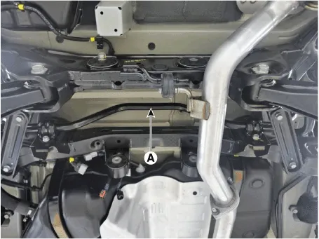
| 4. |
Remove the stabilizer bar (A).
|
| Inspection |
| 1. |
Check the rear stabilizer bar for deformation.
|
| 2. |
Check the rear stabilizer link ball joint for damage.
|
| Installation |
| 1. |
Install in the reverse order of removal.
|
Repair procedures Removal 1. Loosen the wheel nuts slightly. Raise the vehicle, and make sure it is securely supported.
Repair procedures Removal 1. Loosen the wheel nuts slightly. Raise the vehicle, and make sure it is securely supported.
Other information:
Hyundai Palisade (LX2) 2020-2026 Service Manual: Schematic diagrams
System Block Diagram Component Parts And Function Outline Component part Function Vehicle-speed sensor, ESP/ABS Control Module Converts vehicle speed to pulse. ECM Receives signals from sensor and control switches.
Hyundai Palisade (LX2) 2020-2026 Service Manual: Repair procedures
Removal SVM Rear Camera • In case of bad quality or poor focus, be sure to check the camera lense surface condition and foreign materials.
Categories
- Manuals Home
- Hyundai Palisade Owners Manual
- Hyundai Palisade Service Manual
- Emergency liftgate safety release
- Power Outlet
- Convenient Features of Your Vehicle
- New on site
- Most important about car
