Hyundai Palisade (LX2): Rear Suspension System / Rear Cross Member
Repair procedures
| Removal |
| 1. |
Loosen the wheel nuts slightly.
Raise the vehicle, and make sure it is securely supported.
|
| 2. |
Remove the rear wheel and tire (A) from rear hub.
|


| 3. |
Remove the rear brake caliper.
(Refer to Brake System - "Rear Disc Brake")
|
| 4. |
Remove the rear hub carrier.
(Refer to Driveshaft and axle - "Rear Hub -Carrier")
|
| 5. |
In the case of 4WD vehicle, remove the rear differential assembly.
(Refer to Driveshaft and axle - "Rear Differential Carrier")
|
| 6. |
Remvoe the trailing arm.
(Refer to Suspension System - "Trailing Arm")
|
| 7. |
Remove the center muffler.
(Refer to Engine Mechanical System - "Muffler")
|
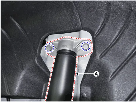
| 8. |
Remove the rear shock absorber (A) from the body by loosening the bolt.
|
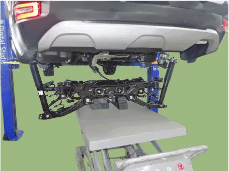
| 9. |
After setting a jack, loosen the bolts and then remove the rear cross
member.
|
| Inspection |
| 1. |
Check the rear stabilizer bar for deformation.
|
| 2. |
Check the rear stabilizer link ball joint for damage.
|
| Installation |
| 1. |
Install in the reverse order of removal.
|
| 2. |
Check the alignment.
(Refer to Suspension System - "Alingment")
|
Repair procedures Removal 1. Raise the vehicle, and make sure it is securely supported. 2. In the case of 4WD vehicle, remove the rear differential assembly.
Other information:
Hyundai Palisade (LX2) 2020-2026 Service Manual: Blower Motor
Repair procedures Inspection 1. Connect the battery voltage and check the blower motor rotation. 2. If the blower motor does not operate well, substitute with a known-good blower motor and check for proper operation.
Hyundai Palisade (LX2) 2020-2026 Service Manual: Front Radar Unit
Specifications Specification Item Specification Power supply (V) 12 Operation voltage (V) 9 - 16 Description and operation Description The smart cruise control unit is installed on the front right-hand side of the chass
Categories
- Manuals Home
- Hyundai Palisade Owners Manual
- Hyundai Palisade Service Manual
- Automatic Transaxle System (A8LF1)
- Rain Sensor
- Electronic Child Safety Lock System
- New on site
- Most important about car
