Hyundai Palisade (LX2): Power Door Locks / Power Door Lock Switch
Repair procedures
| Diagnosis with Diagnostic tool |
| 1. |
In the body electrical system, failure can be quickly diagnosed by using
the vehicle diagnostic system (Diagnostic tool).
The diagnostic system (Diagnostic tool) provides the following information.
|
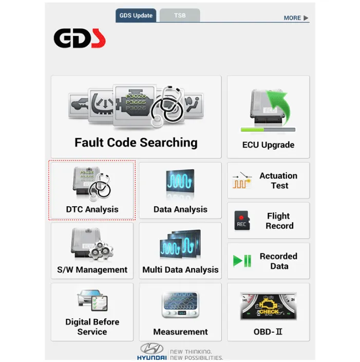
| 2. |
If diagnose the vehicle by Diagnostic tool, select "DTC Analysis" and
"Vehicle".
|
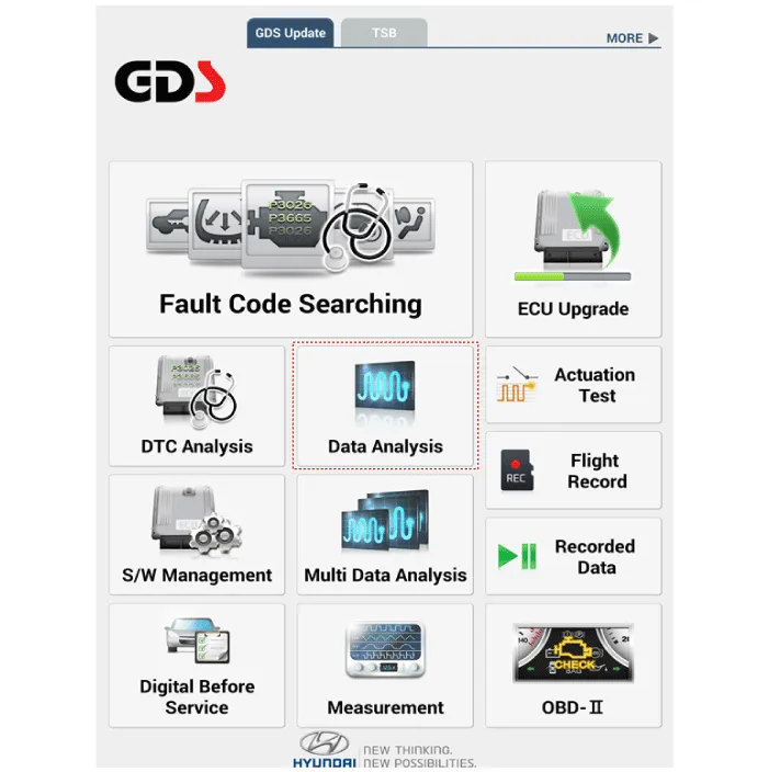
| 3. |
If check current status, select the "Data Analysis" and "Car model".
|
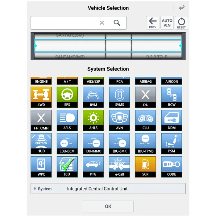
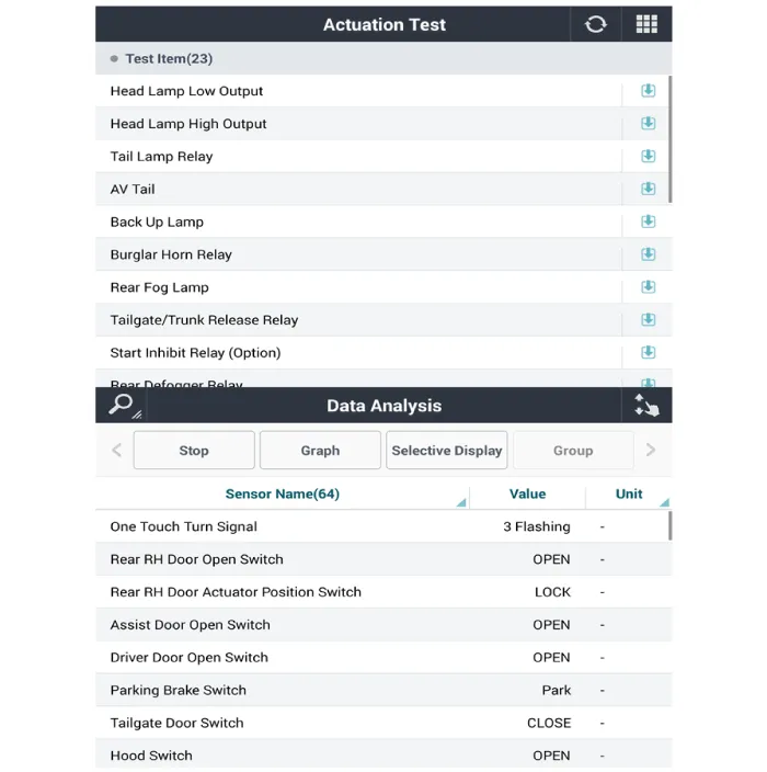
| 4. |
Select the 'ICU' to search the current state of the input/output data.
|
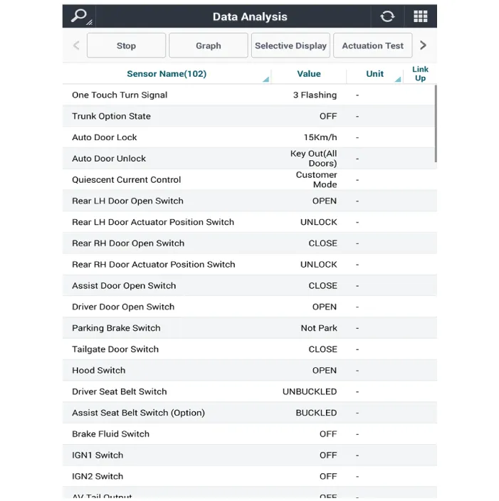
| 5. |
To forcibly actuate the input value of the module to be checked, select
option 'Actuation Test'.
|
| Removal |
| 1. |
Disconnect the negative (-) battery terminal.
|
| 2. |
Remove the front door trim.
(Refer to Body - "Front Door Trim")
|
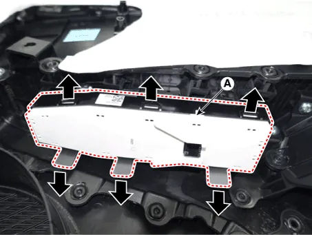
| 3. |
Disengage the mounting clip and then remove the door rock switch assembly
(A).
|
| Installation |
| 1. |
Install the door lock switch assembly.
|
| 2. |
Install the front door trim after connecting the connector.
|
Repair procedures Inspection Front Door Lock Module Inspection 1. Remove the front door trim. (Refer to Body - "Front Door Trim") 2.
Other information:
Hyundai Palisade (LX2) 2020-2026 Service Manual: Description and operating principle
Description and Operation Wireless Power Charger System During ACC or IG ON, battery voltage is supplied to the wireless power charger system to transmit an output of 5 W to mobile phone. Mobile phones certified with the wireless charging standard WPC (Qi 1.
Hyundai Palisade (LX2) 2020-2026 Service Manual: General safety information and caution
General Safety Information and Caution 1. Be careful when driving the vehicle using the smart cruise control system as follows. (1) On curves or inclines/declines • The smart cruise control system may have limits to detect
Categories
- Manuals Home
- Hyundai Palisade Owners Manual
- Hyundai Palisade Service Manual
- Emergency liftgate safety release
- How to reset the power liftgate
- Engine Mechanical System
- New on site
- Most important about car
