Hyundai Palisade (LX2): Automatic Transaxle Control System / Oil Temperature Sensor (Main Harness)
Specifications
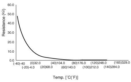
â–· Type: Negative Thermal Coefficient Type
Temp [(°C)°F]
|
Resistance (kΩ)
|
(-40) -40
|
48.1
|
(-20) -4.0
|
15.6
|
(0) 32.0
|
5.88
|
(20) 68.0
|
2.51
|
(40) 104.0
|
1.120
|
(60) 140.0
|
0.612
|
(80) 176.0
|
0.329
|
(100) 212.0
|
0.186
|
(120) 248.0
|
0.109
|
(140) 284.0
|
0.067
|
(150) 302.0
|
0.053
|
Description and operation
| • |
The sensor used is a thermistor (NTC) in which resistance changes with
temperature variation.
|
| • |
Transmission oil temperature sensor monitors the automatic transmission
fluid's temperature and conveys the readings to TCM.
|
| • |
When the TCM supplies about 5 V of power to sensor, the sensor output
value changes depending on ATF temperature.
|
| • |
It is an NTC (Negative Thermal Coefficient) sensor whose resistance
has an inversely proportional relationship with the temperature level.Data
produced by this sensor is used to identify damper clutch activation
and deactivation zones within the low temperature and high temperature
range and to perform hydraulic amendment control during gear changes.
|
| • |
Oil temperature sensor is installed on the valve body and is integrated
with main harness.

|
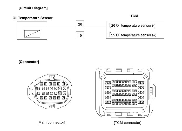
Schematic diagrams
Repair procedures
| • |
Refer to the DTC manual for the check procedure.
|
|
| • |
Be careful not to damage the parts located under the vehicle
(floor under cover, fuel filter, fuel tank and canister) when
raising the vehicle using the lift.
(Refer to General Information - "Lift and Support Points")
|
| • |
When the solenoid valve Diagnostic Trouble Codes (DTC) is on,
perform the following procedure to replace it.
|
| • |
Automatic transaxle is composed of delicate components. Be careful
not to cause any damage on the component in the course of assembly
and disassembly.
|
| • |
Maintain clean condition so that foreign substance does not
get into the automatic transaxle.
|
| • |
Use a coated apron, latex gloves, and stainless tray to prevent
foreign substance from getting into the transaxle.
|
| • |
Automatic transaxle fluid (ATF) can be reused. Collect it using
a clean 10-liter beaker.
|
|
| 1. |
Turn ignition switch OFF and disconnect the negative (-) battery cable.
|
| 2. |
Remove the battery and battery tray.
(Refer to Engine Electrical System - "Battery")
|
| 3. |
Remove the air duct and air cleaner assembly.
(Refer to Engine Mechanical System - "Air Cleaner")
|
| 4. |
Remove the under cover.
(Refer to Engine Mechanical System - "Engine Room Under Cover")
|
| 5. |
Drain the coolant.(If equipped ATF warmer)
(Refer to Engine Mechanical System - "Coolant")
|
| 6. |
Loosen the drain plug (A) and reinstall the drain plug after draining
ATF totally.
|
Tightening torque :
33.3 - 43.1 N.m (3.4 - 4.4 kgf.m, 24.6 - 31.8 lb-ft)
|
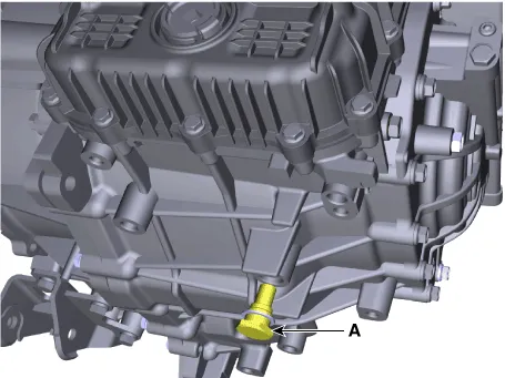
| •
|
Replace the gasket before reinstalling the drain plug.
|
|
|
| 7. |
Loosen the fixing bolt (A) and then removing the bracket.
|
Tightening torque :
9.8 - 11.8 N.m (1.0 - 1.2 kgf.m, 7.2 - 8.7 lb-ft)
|
|
| 8. |
Loosen the fixing bolts (A) and then removing the bracket.
|
Tightening torque :
9.8 - 11.8 N.m (1.0 - 1.2 kgf.m, 7.2 - 8.7 lb-ft)
|
|
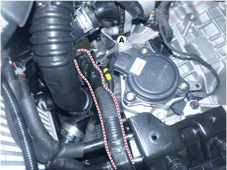
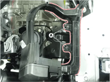
| 9. |
Separate the ATF cooler hose (A).

| •
|
Carefully install the clamp not to damage the hose.
|
| •
|
Install the clamp in a correct direction not to be interfered
with other parts.
|
| •
|
After the installation, start the engine and then check
if there are any leakages from the hose.
|
|
|
| 10. |
Loosen the upper bolts (A) of the valve body cover.
|
Tightening torque :
11.8 - 13.7 N.m (1.2 - 1.4 kgf.m, 8.7 - 10.1 lb-ft)
|
|
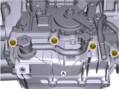
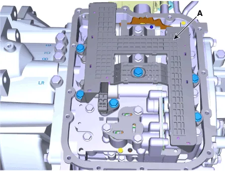
| 11. |
Loosen the bolts and then removing the valve body cover (A).
|
Tightening torque :
11.8 - 13.7 N.m (1.2 - 1.4 kgf.m, 8.7 - 10.1 lb-ft)
|
| •
|
Be careful when removing the valve body cover because
the remaining ATF remains in the valve body cover.
|
|
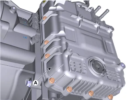
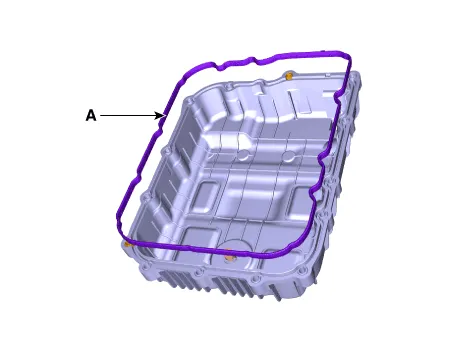
| •
|
Replace the gasket (A) before reinstalling the valve
body cover.
|
| •
|
After the installation, start the engine and then check
if there are any leakages from the valve body cover.
|
|
|
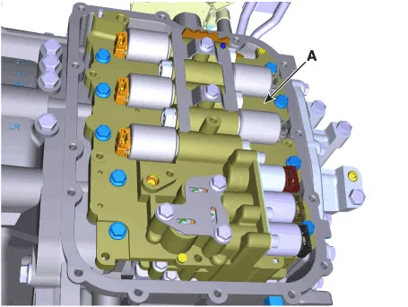
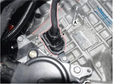
| 12. |
Loosen the bolts and then separate the main harness (A).
|
Tightening torque :
9.8 - 11.8 N.m (1.0 - 1.2 kgf·m, 7.2 - 8.7 lb-ft)
|
|
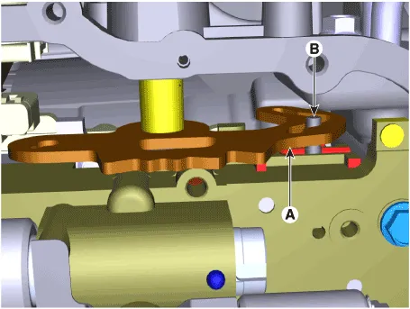
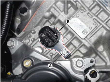
| 13. |
Loosen the bolts and then removing the valve body assembly (A).
|
Tightening torque :
(A) 9.8 - 11.8 N.m (1.0 - 1.2 kgf·m, 7.2 - 8.7 lb-ft)
|
| •
|
Attach the manual pin (B) to the detent lever (A) and
assemble the valve body.
|
|
|
| 14. |
Disconnect the speed sensor connector (A).
|
| 15. |
Disconnect the main connector (A).
|
| 16. |
Loosen the bolt and then removing the fixing of clip (A).
|
Tightening torque :
9.8 - 11.8 N.m (1.0 - 1.2 kgf·m, 7.2 - 8.7 lb-ft)
|
|
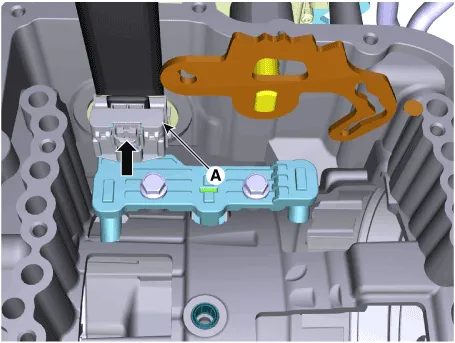
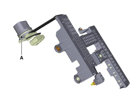
| 17. |
Remove the main connector (B) by pushing it downward.
| •
|
Replace the O-Ring (A) before reinstalling solenoid
valve connector.
|
|
|
| 1. |
To install, reverse the removal procedure.
|
| 2. |
Inject the automatic transaxle oil and inspect the oil level.
(Refer to Automatic Transaxle System - "Automatic Transaxle Fluid")
| •
|
After ATF level check or exchange, be sure to remove
residual ATF on transaxle case.
(Be especially sure to remove residual ATF between automatic
transaxle case and valve body cover)
|
|
|
Description and operation
Description
Controls the 4 position of P(Parking), R, N, D using the rotation of the motor
of according to the electric signal when the shift button is operated.
Specifications
Specification
â–·Type : Hall effect sensor
Item
Specification
Operating condition (°C)°F
(-40 to 150) -40 to 302
Output voltage (V)
High
1.
Other information:
Description and operation
Description
The A/C Pressure Transducer (APT) converts the pressure value of high pressure
line into voltage value after measuring it. By converted voltage value, engine
ECU controls the cooling fan by operating it high speed or low speed.
Repair procedures
Replacement
1.
Disconnect the negative (-) battery terminal.
2.
Remove the heater and blower assembly.
(Refer to Heater - "Heater Unit")
3.


