Hyundai Palisade (LX2): Cooling System / Water Temperature Control Assembly
Repair procedures
| Removal and Installation |
|

|

|

| 1. |
Disconnect the battery negative terminal.
|
| 2. |
Remove the engine cover.
(Refer to Engine and Transaxle Assembly - "Engine Cover")
|
| 3. |
Remove the air duct.
(Refer to Intake and Exhaust System - "Air Cleaner")
|
| 4. |
Disconnect the battery positive terminal.
|
| 5. |
Remove the air cleaner assembly.
(Refer to Intake and Exhaust System - "Air Cleaner")
|
| 6. |
Remove the battery and battery tray.
(Refer to Engine Electrical System - "Battery")
|
| 7. |
Remove the engine room under cover.
(Refer to Engine and Transaxle Assembly - "Engine Room Under Cover")
|
| 8. |
Drain the engine coolant.
(Refer to Cooling System - "Coolant")
|
| 9. |
Disconnect the radiator upper hose (A).
|

| 10. |
Disconnect the radiator lower hose (A).
|
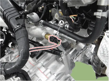
| 11. |
Disconnect the water temperature sensor connector (A).
|
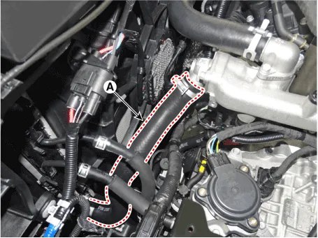
| 12. |
Disconnect the control wiring harness connectors and fasteners and remove
the wiring harness protectors from the water temperature control assembly.
|

| 13. |
Disconnect the heater hoses (A).
|
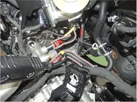
| 14. |
Disconnect the ATF warmer hose (A).
|

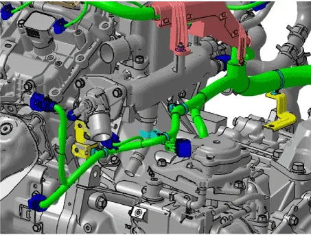
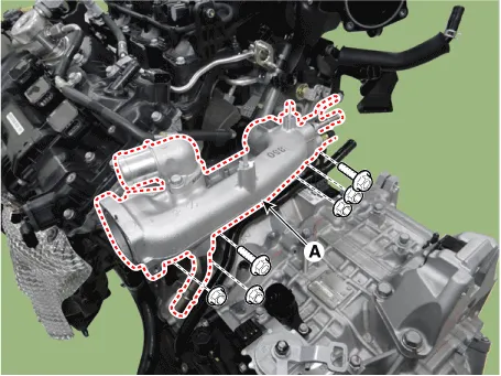
| 15. |
Remove the water temperature control assembly (A).
|
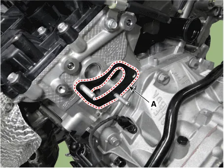
| 16. |
Remove the water temperature control assembly gasket (A).
[LH]
[RH]
|


| 17. |
Install in the reverse order of removal.
|
| 18. |
Fill the radiator with coolant.
(Refer to Cooling System - "Coolant")
|
| 19. |
Start engine and check for leaks.
|
| 20. |
Recheck the coolant level.
|
|

| 1. |
Remove the water temperature control assembly.
|
| 2. |
Remove the surge tank.
(Refer to Intake and Exhaust System - "Surge Tank")
|
| 3. |
Remove the intake manifold.
(Refer to Intake and Exhaust System - "Intake Manifold")
|
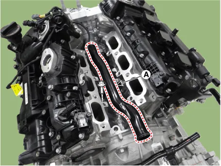
| 4. |
Remove the water center pipe (A).
|

| 5. |
Install in the reverse order of removal.
|
Repair procedures Removal and Installation 1. Disconnect the over flow hose (A). 2. Remove the reservoir tank (B).
Components and components location Components 1. Water pump pulley 2. Water pump 3. Water pump gasket Repair procedures Removal • Be careful not to damage the parts located under the vehicle (floor under cover, fuel filter, fuel tank and canister) when raising the vehicle using the lift.
Other information:
Hyundai Palisade (LX2) 2020-2026 Service Manual: Description and operating principle
Description and Operation Wireless Power Charger System During ACC or IG ON, battery voltage is supplied to the wireless power charger system to transmit an output of 5 W to mobile phone. Mobile phones certified with the wireless charging standard WPC (Qi 1.
Hyundai Palisade (LX2) 2020-2026 Service Manual: Rear Heater Core
Repair procedures Replacement 1. Remove the rear heater & A/C unit. (Refer to Rear Heater - "Rear Heater Unit") 2. Loosen the mounting screws and remove the rear heater core cover (A).
Categories
- Manuals Home
- Hyundai Palisade Owners Manual
- Hyundai Palisade Service Manual
- Removing and Storing the Spare Tire
- Maintenance
- Convenient Features of Your Vehicle
- New on site
- Most important about car
