Hyundai Palisade (LX2): Blower / Intake Actuator
Hyundai Palisade (LX2) 2020-2026 Service Manual / Heating,Ventilation And Air Conditioning / Blower / Intake Actuator
Description and operation
| Description |
The intake actuator is located at the blower unit. It regulates the intake door
by a signal from the control unit. Pressing the intake selection switch will
shift between recirculation and fresh air modes.
Components and components location
| Components |

| 1. Intake actuator |
Repair procedures
| Inspection |
| 1. |
Turn the ignition switch OFF.
|
| 2. |
Disconnect the intake actuator connector.
|
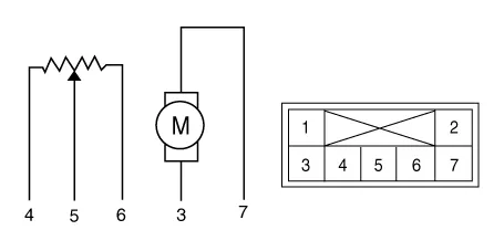
| 3. |
Verify that the intake actuator operates to the fresh air position when
connecting 12V to terminal 3 and grounding terminal 7.
Verify that the intake actuator operates to the recirculated air position
when connected in reverse.
|
| 4. |
Connect the intake actuator connector.
|
| 5. |
Turn the ignition switch ON.
|
| 6. |
Check the voltage between terminal 5 and 6.
Specification
It will feedback the current position of the actuator to controls.
|
| 7. |
If the intake actuator does not operate well, substitute with a known-good
intake actuator and check for proper operation.
|
| 8. |
Replace the intake actuator if it is proved that there is a problem
with it.
|
| Replacement |
| 1. |
Disconnect the negative (-) battery terminal.
|
| 2. |
Remove the main crash pad assembly.
(Refer to Body - "Main Crash Pad Assembly")
|
| 3. |
Separate the intake actuator connector (A), loosen the mounting screws
and remove the intake actuator (B).
|

| 4. |
Install in the reverse order of removal.
|
Description and operation Description The climate control air filter is located in the blower unit. It eliminates foreign materials and odor.
Other information:
Hyundai Palisade (LX2) 2020-2026 Service Manual: General safety information and caution
Instructions (R-134a) When Handling Refrigerant 1. R-134a liquid refrigerant is highly volatile. A drop on the skin of your hand could result in localized frostbite. When handling the refrigerant, be sure to wear gloves.
Hyundai Palisade (LX2) 2020-2026 Service Manual: Troubleshooting
Trouble Symptom Charts Trouble Symptom 1 Trouble Symptom 2 Trouble symptom Probable cause Remedy The set vehicle speed varies greatly upward or downward "Surging" (repeated alternating acceleration and deceleration) occurs after set
Categories
- Manuals Home
- Hyundai Palisade Owners Manual
- Hyundai Palisade Service Manual
- Electrochromatic Mirror (ECM) with homelink system
- Electronic Child Safety Lock System
- Automatic Transaxle Fluid (ATF)
- New on site
- Most important about car

Copyright © 2026 www.hpalisadelx.com - 0.0276