Hyundai Palisade (LX2): Hydraulic System / Valve Body
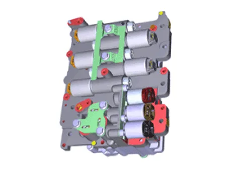
Description and operation
| Description |
| • |
The valve body mounted is inside the transaxle.
|
| • |
The valve body is essential to automatic transaxle control and consists
of various valves used to control the oil feed from the oil pump.
|
| • |
Specifically, these valves consist of pressure regulator valves, oil
redirection valves, shift valves, and manual valves.
|
| • |
The body also features electronic solenoid valves that ensure smooth
gear changes.
|
Repair procedures
| Removal |
|

| 1. |
Turn ignition switch OFF and disconnect the negative (-) battery cable.
|
| 2. |
Remove the battery and battery tray.
(Refer to Engine Electrical System - "Battery")
|
| 3. |
Remove the air duct and air cleaner assembly.
(Refer to Engine Mechanical System - "Air Cleaner")
|
| 4. |
Remove the under cover.
(Refer to Engine Mechanical System - "Engine Room Under Cover")
|
| 5. |
Drain the coolant.(If equipped ATF warmer)
(Refer to Engine Mechanical System - "Coolant")
|
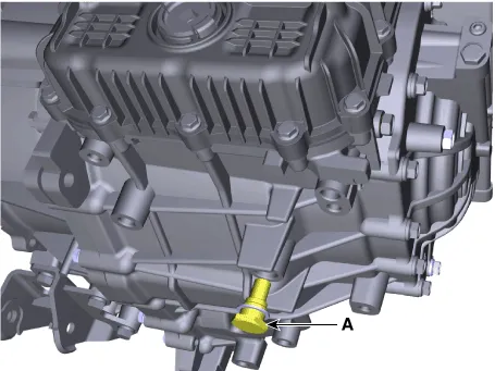
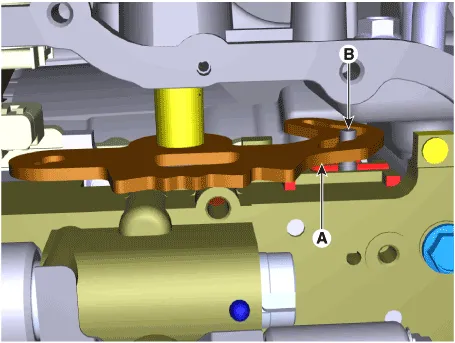
| 6. |
Loosen the drain plug (A) and reinstall the drain plug after draining
ATF totally.
|

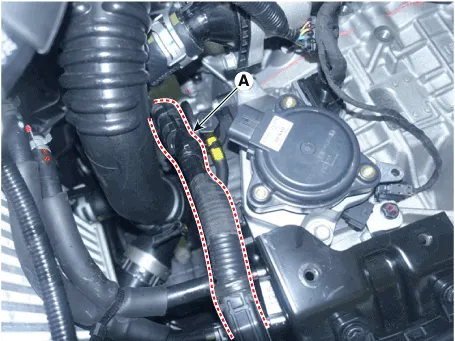
| 7. |
Loosen the fixing bolt (A) and then removing the bracket.
|
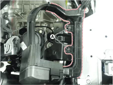
| 8. |
Loosen the fixing bolts (A) and then removing the bracket.
|
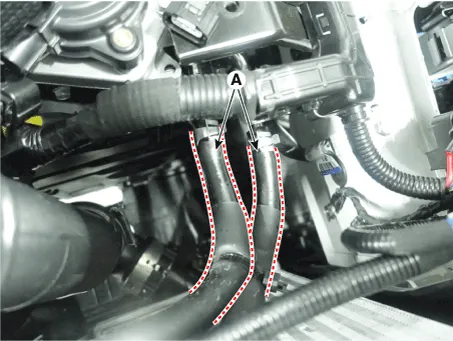
| 9. |
Separate the ATF cooler hose (A).
|

| 10. |
Loosen the upper bolts (A) of the valve body cover.
|

| 11. |
Remove the valve body cover (A) after removing the bolts.
|


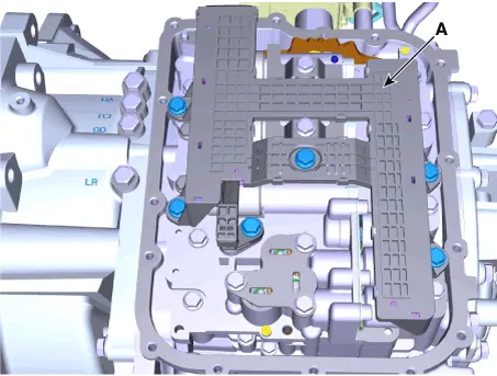
| 12. |
Loosen the bolts and then Separate the main harness (A).
|
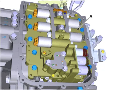
| 13. |
Remove the valve body assembly (A).
|

| Installation |
| 1. |
To install, reverse the removal procedures.
|
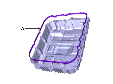
| 2. |
The existing valve body cover gasket (A) must be replaced with a new
one. (Do not reuse it.)
|

| 3. |
Perform the procedures below after in replacing the valve body assembly.
|
| 4. |
Refill the automatic transaxle with fluid.
(Refer to Hydraulic System - "Fluid")
|
| 5. |
Add the coolant. [In case by ATF warmer apply]
(Refer to Engine Mechanical System - "Coolant")
|
| 6. |
Clear the diagnostic trouble codes (DTC) using the diagnostic tool.
Disconnecting the battery negative terminal will not clear the DTCs.
Clear DTCs using the diagnostic tool at all times.
|
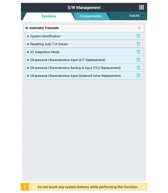
| 7. |
Reset the automatic transaxle adaptive values using the diagnostic tool.
|
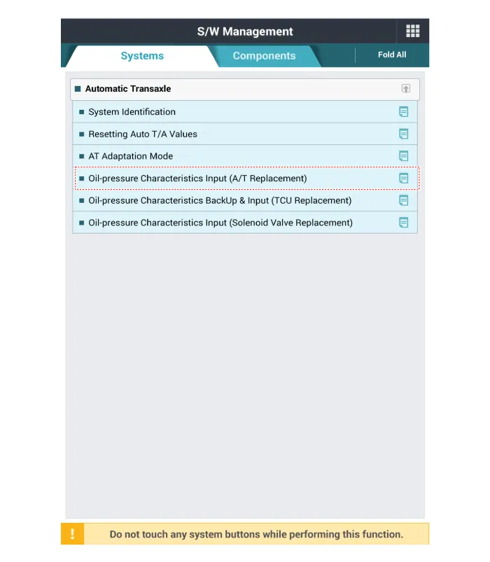
| 8. |
Perform the oil pressure characteristics input procedure using the diagnostic
tool.
|
| 9. |
Perform the TCM adaptive values learning procedure.
(Refer to Automatic Transaxle Control System - "Repair procedures")
|
| 10. |
After installing, check for leakage of fluid from hose connection during
engine start.
|
Repair procedures Removal 1. Turn ignition switch OFF and disconnect the negative (-) battery cable. 2.
Description and operation Description • Torque converter control solenoid valve (T/CON_VFS) is attached to the valve body.
Other information:
Hyundai Palisade (LX2) 2020-2026 Service Manual: Condenser
C
Hyundai Palisade (LX2) 2020-2026 Service Manual: Description and operation
Description Rear view camera will activate when the backup light is ON with the ignition switch ON and the shift lever in the R position. This system is a supplemental system that shows behind the vehicle through the AV monitor or the ECM (Reverse Display Room Mirror) mirror while backing-up.
Categories
- Manuals Home
- Hyundai Palisade Owners Manual
- Hyundai Palisade Service Manual
- General Tightening Torque Table
- Electrochromatic Mirror (ECM) with homelink system
- Repair procedures
- New on site
- Most important about car

Copyright © 2026 www.hpalisadelx.com - 0.0169