Hyundai Palisade (LX2): Timing System / Timing Chain Cover
Repair procedures
| Removal |
|

|

|

|

| 1. |
Remove the engine cover.
(Refer to Engine And Transaxle Assembly - "Engine Cover")
|
| 2. |
Remove the engine room under cover.
(Refer to Engine And Transaxle Assembly - "Engine Room Under Cover")
|
| 3. |
Drain the engine coolant.
(Refer to Cooling System - "Coolant")
|
| 4. |
Drain the engine oil.
(Refer to Lubrication System - "Engine Oil")
|
| 5. |
Remove the air cleaner assembly.
(Refer to Intake And Exhaust System - "Air Cleaner")
|
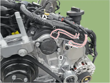
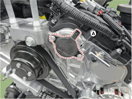
| 6. |
Disconnect the variable force solenoid (VFS) valve connector (A) and
ground cable (B).
|
| 7. |
Remove the surge tank.
(Refer to Intake And Exhaust System - "Surge Tank")
|
| 8. |
Remove the LH / RH cylinder head cover.
(Refer to Cylinder Head Assembly - "Cylinder Head Cover")
|
| 9. |
Remove the drive belt.
(Refer to Timing System - "Drive Belt")
|
| 10. |
Remove the idler.
(Refer to Timing System - "Idler")
|
| 11. |
Remove the drive belt tensioner.
(Refer to Timing System - "Drive Belt Tensioner")
|
| 12. |
Remove the crankshaft damper pulley.
(Refer to Timing System - "Crankshaft Damper Pulley")
|
| 13. |
Remove the water pump.
(Refer to Cooling System - "Water Pump")
|
| 14. |
Remove the lower oil pan.
(Refer to Lubrication System - "Oil Pan")
|
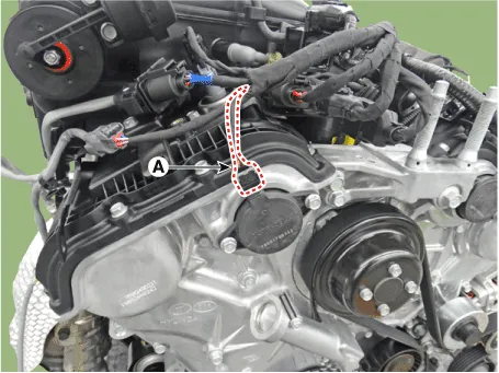
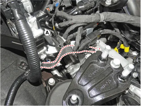
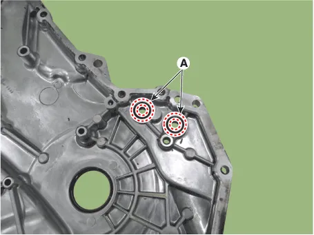
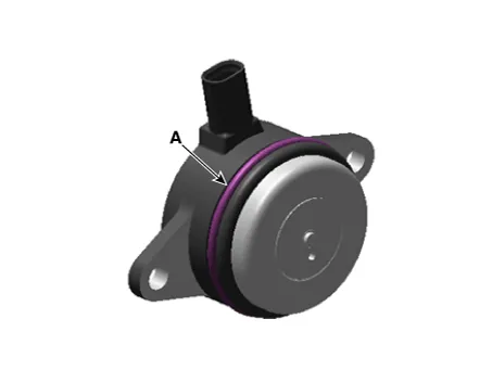
| 15. |
Remove the RH and LH variable force solenoid (VFS) valve (A).
[RH]
[LH]
|


| 16. |
Remove the engine mounting support bracket.
|

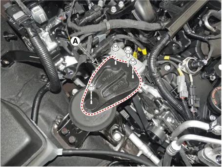
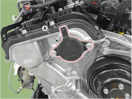
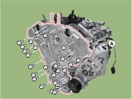
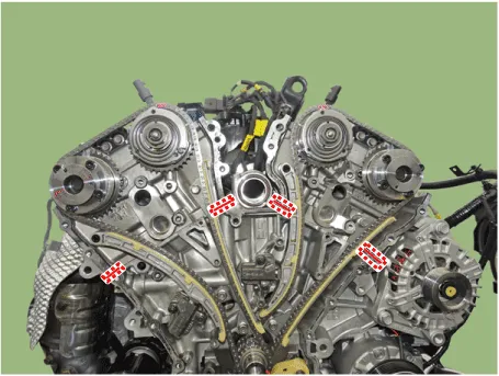
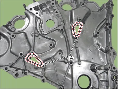
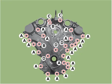
| 17. |
Remove the timing chain cover (A).
|

| Installation |
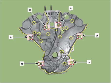
| 1. |
Install the timing chain cover.
|


| 2. |
Install the engine mounting support bracket.
|


| 3. |
Install the RH and LH variable force solenoid (VFS) valve (A).
[RH]
[LH]
|


| 4. |
Install the remaining parts in the reverse order of removal.
|

Repair procedures Removal • Be careful not to damage the parts located under the vehicle (floor under cover, fuel filter, fuel tank and canister) when raising the vehicle using the lift.
Repair procedures Removal • Be careful not to damage the parts located under the vehicle (floor under cover, fuel filter, fuel tank and canister) when raising the vehicle using the lift.
Other information:
Hyundai Palisade (LX2) 2020-2026 Service Manual: Description and operation
Description Blind-Spot Radar is a system that measures the relative speed and distance from the following vehicles by using two electromagnetic wave radar sensors attached to the rear bumper, and detects any vehicle within the blind spot zone and gives off alarm (visual and auditory).
Hyundai Palisade (LX2) 2020-2026 Service Manual: Surround View Monitor (SVM) Unit
Components and components location Components No Connector A 1 ACC 2 LED 3 EXT Ground 4 Y Shield 5 - 6 C-CAN Low 7
Categories
- Manuals Home
- Hyundai Palisade Owners Manual
- Hyundai Palisade Service Manual
- Removing and Storing the Spare Tire
- Electronic Child Safety Lock System
- Maintenance
- New on site
- Most important about car
