Hyundai Palisade (LX2): Smart Key System / Smart Key Diagnostic
Repair procedures
| Inspection |
| 1. |
Problem in SMART KEY unit input.
|
| 2. |
Problem in SMART KEY unit.
|
| 3. |
Problem in SMART KEY unit output.
|
| 4. |
SMART KEY unit Input problem : switch diagnosis
|
| 5. |
SMART KEY unit problem : communication diagnosis
|
| 6. |
SMART KEY unit Output problem : antenna and switch output diagnosis
|
| 1. |
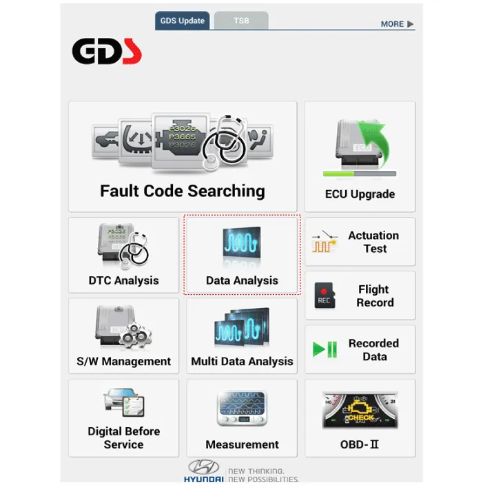
In the body electrical system, failure can be quickly diagnosed by using
the vehicle diagnostic system (Diagnostic tool).
The diagnostic system(Diagnostic tool) provides the following information.
|
| 2. |
If diagnose the vehicle by Diagnostic tool, select "DTC Analysis" and
"Vehicle".
|

| 3. |
If check current status, select the "Data Analysis" and "Car model".
|
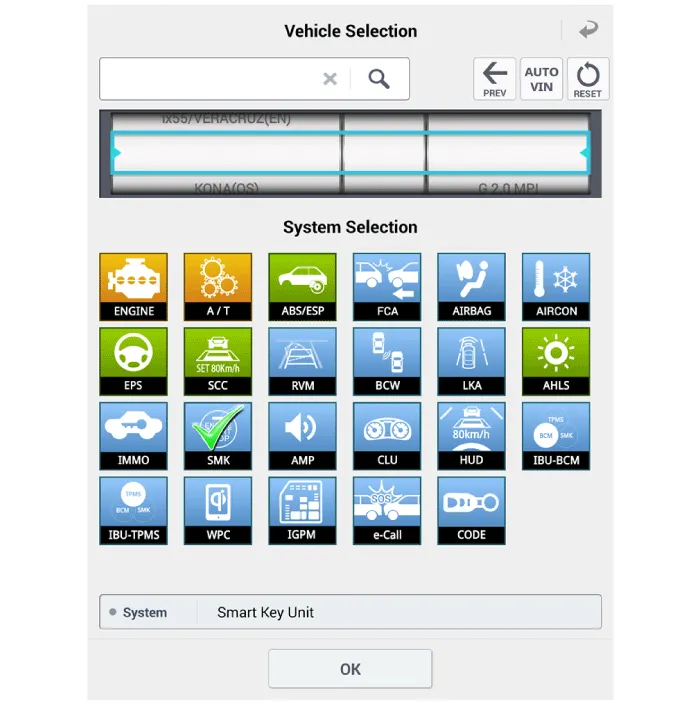
| 4. |
Select the SMK' to be checked in order to check the vehicle with the
tester.
|
| 5. |
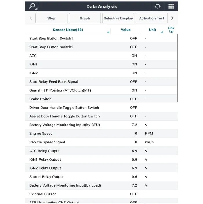
You can see the situation of each switch on scanner after connecting
the "current data" process.
|
| 1. |
Fault code searching that the each linked components operates normal.
|
| 2. |
Connect the cable of Diagnostic tool to the data link connector in driver
side crash pad lower panel.
|
| 3. |
Select the 'Fault Code Searching' and 'Car model'.
|

| 1. |
Connect the cable of Diagnostic tool to the data link connector in driver
side crash pad lower panel.
|
| 2. |
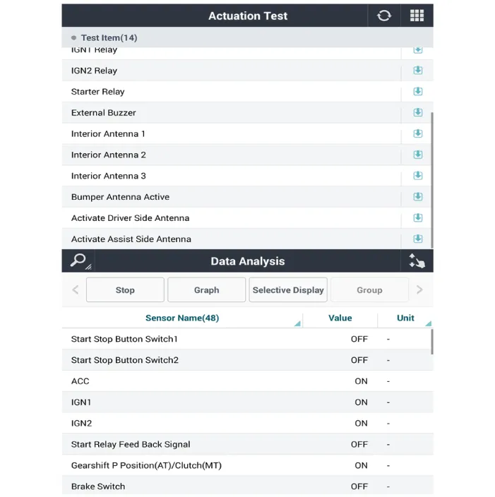
Select the 'Actuation Test' and 'Car model'.
|

| 3. |
Set the smart key near the related antenna and operate it with a Diagnostic
tool.
|
| 4. |
Set the smart key near the related antenna and operate it with a Diagnostic
tool.
|
| 5. |
If the LED of smart key is blinking, the smart key is normal.
|
| 6. |
If the LED of smart key is not blinking, check the voltage of smart
key battery.
|
| 7. |
Antenna actuation
|
| 1. |
Connect the cable of Diagnostic tool to the data link connector in driver
side crash pad lower panel.
|
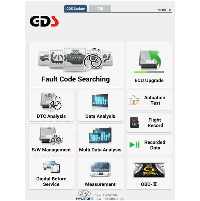
| 2. |
Select the 'S/W Management' and 'Car model'.
|

| 3. |
Select the 'Smart Key Unit' and 'Antenna Status Check'.
|

| 4. |
Set the smart key near the related antenna and operate it with a Diagnostic
tool.
|
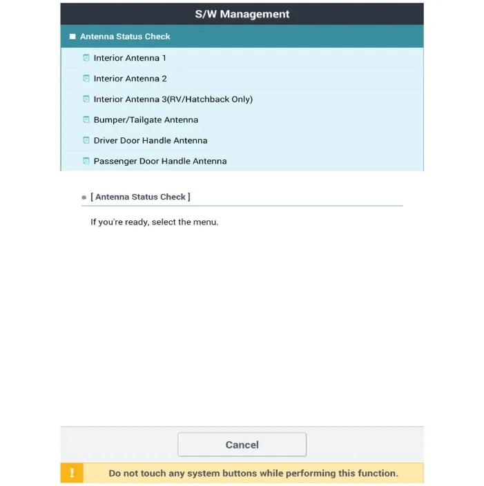
| 5. |
If the smart key runs normal , the related antenna, smart key (transmission,
reception) and exterior receiver are normal.
|
| 6. |
Antenna status
|
| 1. |
Connect the cable of Diagnostic tool to the data link connector in driver
side crash pad lower panel.
|
| 2. |
Select the 'S/W Management' and 'Car model'.
|

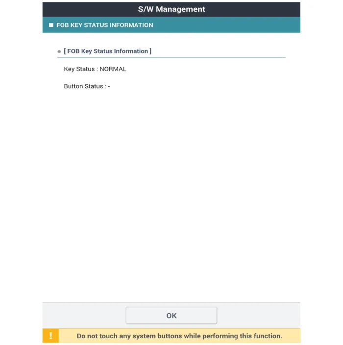
| 3. |
Select the 'Smart Key Unit' and 'FOB KEY STATUS IMFORMATION'.
|

| 1. |
Connect the cable of Diagnostic tool to the data link connector in driver
side crash pad lower panel.
|
| 2. |
Select the 'S/W Management' and 'Car model'.
|
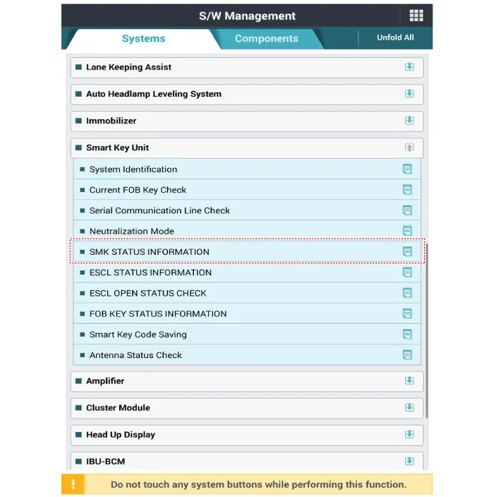
| 3. |
Select the 'Smart Key Unit' and 'SMK STATUS INFORMATION'.
|
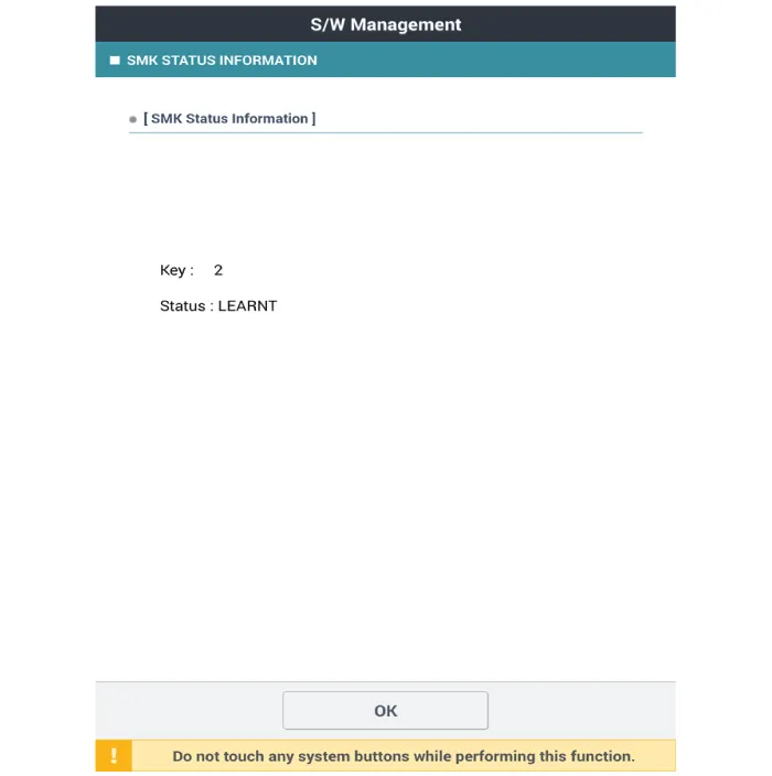
| 1. |
Connect the cable of Diagnostic tool to the data link connector in driver
side crash pad lower panel.
|
| 2. |
Select the 'S/W Management' and 'Car model'.
|

| 3. |
Select the 'Smart Key Unit' and 'Neutralization Mode'.
|


Components and components location Components (1) Connector Pin Information No Connector A Connector B Connector C 1 - GND_ECU Front wiper relay (Low)_output 2 - PDW-F power_output ESCL (+)_output 3 GND_Power ESCL (-)_output Start relay_output 4 PDW-R_Power_Output Front wiper high relay_output IGN1 relay_output 5 - PDW-R WIND_output Immobilizer antenna power_output 6 Rear washer switch_input - Immobilizer antenna ground_output 7 LIN4 (Rear seat remind) - - 8 P_CAN (Low) Rear view switch_input Interior1 antenna (+)_output 9 P_CAN (High) - Driver outside handle antenna(+)_output 10 - Wheel speed sensor_input - 11 B_CAN (Low) - Passenger outside handle antenna(+)_output 12 B_CAN (High) 3rd line sheet belt indicator RH_output - 13 SSB switch_input Passenger seat belt indicator_output Trunk interior antenna3(+)_output 14 Driver handle antenna switch_input Rear center seat belt indicator_output Immobilizer K-Line 15 P position_input (AT) - Bumper antenna (+)_output - 16 Fog switch_input LF searching_output Interior antenna2(+)_output 17 Light switch_input Auto light sensor signal_input IGN2_input 18 Front wiper INT volume switch_input Auto light sensor power_output IGN1_input 19 Multifunction switch_input ATM solenoid_output IGN2 relay_output 20 Right side mirror unfolding switch_oupout Puddle pocket lamp_output Battery_power 21 Right side mirror heater_output - Brake switch_input 22 Front washer switch_input SSB ring illumination_output Start feedback_input 23 Front wiper low switch_Input piezo buzzer_output Security indicator_output 24 LIN1 (PDW) SSB symbol illumination_output Interior1 (-)_output 25 LIN2 (Safety ECU) 3rd line sheet belt indicator_output Driver outside handle antenna (-)_output 26 LIN3 (Rain sensor) Wiper power relay_output - 27 PDW power_input Rear seat belt indicator RH_output Passenger outside handle antenna (-)_output 28 PDW_input Rear seat belt indicator LH_output ESCL COM 29 SSB switch1_input 3rd line sheet belt indicator LH_output Trunk Interior antenna3(-)_output 30 ESCL unlock_input Rear wiper relay_output ESCL Enable_output 31 Passenger outside handle switch_input Auto light sensor ground_output Bumper antenna (-)_output 32 PDW switch_input Wiper parking switch_input Interior antenna2 (-)_output 33 Sun roof Status_input ACC_input 34 Head lamp switch_input Mirror power_input 35 Front wiper switch_input ACC relay_output 36 Rear wiper switch_input ECU battery (+) 37 Mirror folding RH_output 38 Mirror RH VT_output
Other information:
Hyundai Palisade (LX2) 2020-2026 Service Manual: Photo Sensor
Description and operation Description The photo sensor is located at the center of the defrost nozzles. The photo sensor contains a photovoltaic (sensitive to sunlight) diode. The solar radiation received by its light receiving portion, generates an electromotive force in proportion to the amount of radiation received wh
Hyundai Palisade (LX2) 2020-2026 Service Manual: Schematic diagrams
Trouble Symptom Charts Component Parts and Function Outline Component part Function Cruise Control Switch Input the set speed and distance to the SCC ECU. Instrument Cluster Display various information inputted from SCC.
Categories
- Manuals Home
- Hyundai Palisade Owners Manual
- Hyundai Palisade Service Manual
- Scheduled maintenance services
- Engine Mechanical System
- Rear Heater Unit
- New on site
- Most important about car
