
Hyundai Palisade (LX2): ESP(Electronic Stability Program) System / Schematic diagrams
| Circuit Diagram |
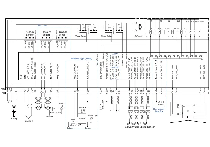
| Terminal Function |

|
PIN No |
Desciption |
Current |
|
|
Max |
Min |
||
|
1 |
Voltage supply for pump motor |
39A |
10 MΩ |
|
2 |
RR EPB motor power |
30A |
10 MΩ |
|
3 |
RR EPB motor ground |
30A |
10 MΩ |
|
4 |
Clutch stroke sensor signal |
- |
- |
|
5 |
Local CAN High |
30 mA |
- |
|
6 |
Electric parking brake signal 1 |
20 mA |
250 MΩ |
|
7 |
Electric parking brake signal 2 |
20 mA |
250 MΩ |
|
8 |
Electric parking brake signal 3 |
20 mA |
250 MΩ |
|
9 |
Electric parking brake signal 4 |
20 mA |
250 MΩ |
|
10 |
- |
- |
250 MΩ |
|
11 |
- |
- |
- |
|
12 |
RL EPB motor ground |
30A |
- |
|
13 |
RL EPB motor power |
30A |
10 MΩ |
|
14 |
Ground for solenoid valves and ECU |
30A |
10 MΩ |
|
15 |
- |
- |
10 MΩ |
|
16 |
- |
- |
250 MΩ |
|
17 |
ESP OFF switch signal |
16.8 mA |
|
|
18 |
N' Signal |
- |
250 MΩ |
|
19 |
Local CAN High |
10 mA |
250 MΩ |
|
20 |
Local CAN Low |
30 mA |
250 MΩ |
|
21 |
- |
- |
250 MΩ |
|
22 |
P-CAN LOW |
- |
|
|
23 |
P-CAN High |
200 mA |
250 MΩ |
|
24 |
- |
- |
250 MΩ |
|
25 |
Wheel speed sensor supply voltage (RL) |
16.8 mA |
|
|
26 |
Wheel speed sensor supply voltage (RR) |
16.8 mA |
250 MΩ |
|
27 |
Wheel speed sensor supply voltage (FR) |
16.8 mA |
250 MΩ |
|
28 |
Wheel speed sensor supply voltage (FL) |
- |
250 MΩ |
|
29 |
- |
16.8 mA |
250 MΩ |
|
30 |
Voltage supply for solenoid valves |
30A |
|
|
31 |
- |
- |
10 MΩ |
|
32 |
- |
Open drain |
|
|
33 |
- |
- |
|
|
34 |
Auto holding ON/OFF switch signal |
10 mA |
|
|
35 |
Brake light switch |
10 mA |
250 MΩ |
|
36 |
HAC / BLA signal output |
16.8 mA |
250 MΩ |
|
37 |
IGN 1 |
5A |
250 MΩ |
|
38 |
ESS signal output |
16.8 mA |
50 MΩ |
|
39 |
- |
16.8 mA |
250 MΩ |
|
40 |
- |
- |
|
|
41 |
- |
- |
|
|
42 |
- |
- |
250 MΩ |
|
43 |
- |
- |
250 MΩ |
|
44 |
Wheel speed sensor ground (FL) |
30 mA |
250 MΩ |
|
45 |
Wheel speed sensor ground (FR) |
30 mA |
250 MΩ |
|
46 |
Recirculation pump ground |
40A |
250 MΩ |
Description of ESP ESP recognizes critical driving conditions, such as panic reactions in dangerous situations, and stabilizes the vehicle by wheel-individual braking and engine control intervention.
Failure Diagnosis 1. In principle, ESP and TCS controls are prohibited in case of ABS failure. 2. When ESP or TCS fails, only the failed system control is prohibited.
Other information:
Hyundai Palisade (LX2) 2020-2026 Service Manual: Components and components location
Component Location 1. Start Stop Button(SSB) 2. FOB key 3. Tailgate open switch 4. Interior antenna 1 5. Interior antenna 2 6. Intergrated Body Control Unit (IBU) 7. Trunk antenna 8. Door handle & door antenna 9.
Hyundai Palisade (LX2) 2020-2026 Service Manual: Description and operation
Description The cruise control system is engaged by the cruise "ON/OFF" main switch located on right of steering wheel column. The system has the capability to cruise, coast, accelerate and resume speed. It also has a safety interrupt, engaged upon depressing brake or shifting select lever.
Categories
- Manuals Home
- Hyundai Palisade Owners Manual
- Hyundai Palisade Service Manual
- Electronic Child Safety Lock System
- Engine Control/Fuel System
- Removing and Storing the Spare Tire
- New on site
- Most important about car
