Hyundai Palisade (LX2): ESP(Electronic Stability Program) System / Description and operation
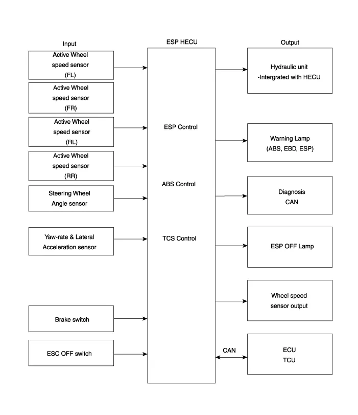
| Description of ESP |
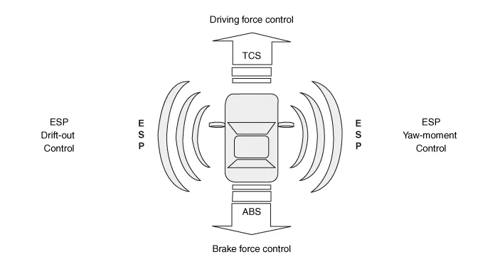
| ESP Operation Mode |
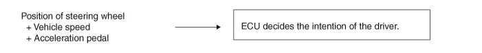
| 1. |
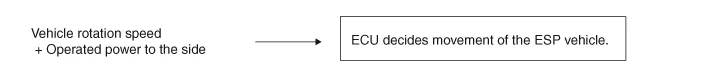
STEP 1
The ESP analyzes the intention of the driver.
|
| 2. |
STEP 2
It analyzes the movement of the ESP vehicle.
|
| 3. |
STEP 3
The HECU calculates the required strategy, then actuates the appropriate
valves and sents torque control requests via CAN to maintain vehicle
stability.
|
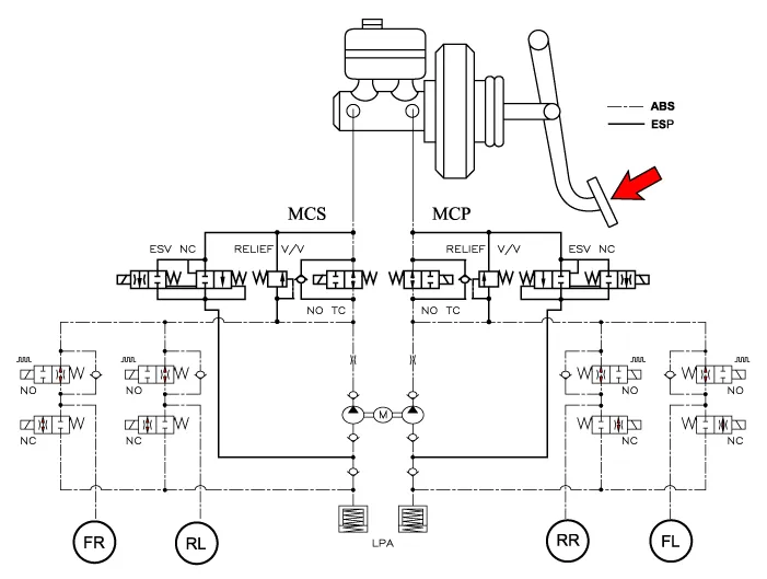
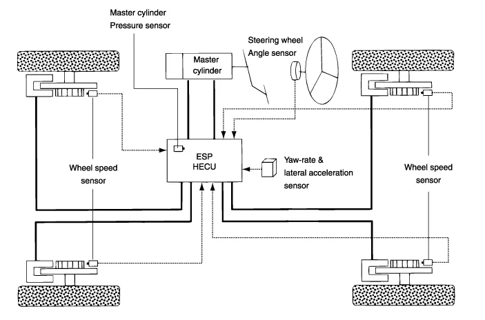
| ESP Hydraulic System Diagram |
| 1. |
ESP Non-operation : Normal braking.
|
| 2. |
ESP operation
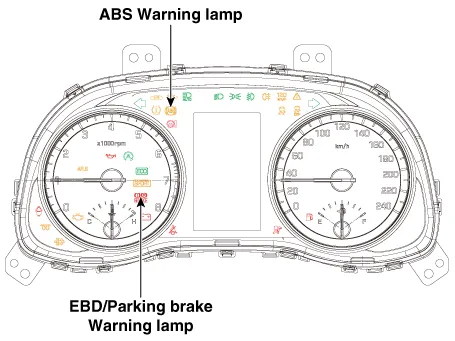
Warning Lamp Control
|
||||||||||||||||||||||
| – |
During the initialization phase after IGN ON. (continuously 3 seconds).
|
| – |
In the event of inhibition of ABS functions by failure.
|
| – |
During diagnostic mode.
|
| – |
When the ECU Connector is seperated from ECU.
|
| – |
Cluster lamp is ON when communication is impossible with CAN module.
|
| – |
During the initialization phase after IGN ON. (continuously 3 seconds).
|
| – |
When the Parking Brake Switch is ON or brake fluid level is low.
|
| – |
When the EBD function is out of order .
|
| – |
During diagnostic mode.
|
| – |
When the ECU Connector is seperated from ECU.
|
| – |
Cluster lamp is ON when communication is impossible with CAN module.
|
| – |
During the initialization phase after IGN ON. (continuously 3 seconds).
|
| – |
When the ESP function is inhibited by system failure.
|
| – |
When the ESP control is operating. (Blinking - 2Hz)
|
| – |
During diagnostic mode.(Except standard mode)
|
| – |
Cluster lamp is ON when communication is impossible with CAN module.
|
| – |
During the initialization mode after IGN ON. (continuously 3 seconds).
|
| – |
ESP Off lamp is On when driver input the ESP Off switch.
|
Components 1. ABS control module (HECU) 2. Front wheel speed sensor 3. Rear wheel speed sensor 4. ABS warning lamp 5.
Circuit Diagram Terminal Function PIN No Desciption Current Max Min 1 Voltage supply for pump motor 39A 10 MΩ 2 RR EPB motor power 30A 10 MΩ 3 RR EPB motor ground 30A 10 MΩ 4 Clutch stroke sensor signal - - 5 Local CAN High 30 mA - 6 Electric parking brake signal 1 20 mA 250 MΩ 7 Electric parking brake signal 2 20 mA 250 MΩ 8 Electric parking brake signal 3 20 mA 250 MΩ 9 Electric parking brake signal 4 20 mA 250 MΩ 10 - - 250 MΩ 11 - - - 12 RL EPB motor ground 30A - 13 RL EPB motor power 30A 10 MΩ 14 Ground for solenoid valves and ECU 30A 10 MΩ 15 - - 10 MΩ 16 - - 250 MΩ 17 ESP OFF switch signal 16.
Other information:
Hyundai Palisade (LX2) 2020-2026 Service Manual: Mode Control Actuator
Description and operation Description The mode control actuator is located at the heater unit. It adjusts the position of the mode door by operating the mode control actuator based on the signal of the A/C control unit. Pressing the mode select switch makes the mode control actuator shift in order of Vent → Bi-Level →
Hyundai Palisade (LX2) 2020-2026 Service Manual: Repair procedures
Inspection 1. Turn the ignition switch ON. 2. Manually operate the control switch and measure the voltage of the blower motor. 3. Select the control switch to raise the voltage until it reaches high speed.
Categories
- Manuals Home
- Hyundai Palisade Owners Manual
- Hyundai Palisade Service Manual
- Engine Mechanical System
- Automatic Transaxle System (A8LF1)
- Body Electrical System
- New on site
- Most important about car
