
Hyundai Palisade (LX2): Rear Axle Assembly / Rear Hub - Carrier
Hyundai Palisade (LX2) 2020-2026 Service Manual / Driveshaft and axle / Rear Axle Assembly / Rear Hub - Carrier
Components and components location
| Components |
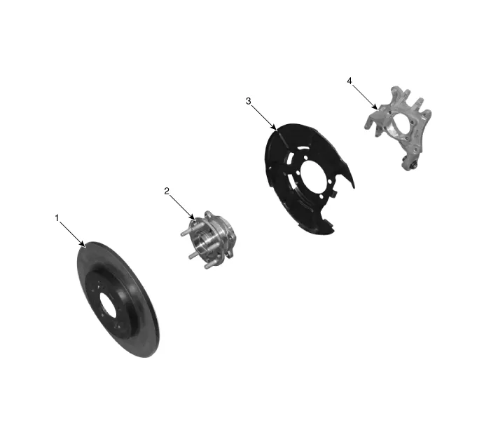
| 1. Rear brake disc 2. Rear hub assembly |
3. Dust cover 4. Rear carrier assembly |
Repair procedures
| Removal |
| 1. |
Loosen the wheel nuts slightly.
Raise the vehicle, and make sure it is securely supported.
|
| 2. |
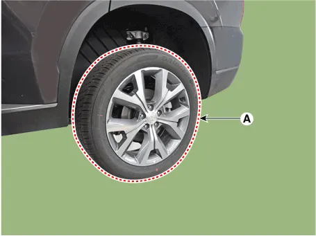
Remove the rear wheel and tire (A) from rear hub.
|

| 3. |
Remove the rear brake caliper.
(Refer to Brake System - "Rear Disc Brake")
|
| 4. |
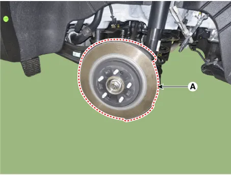
Loosen the screw and then removing the rear brake disc (A).
|
| 5. |
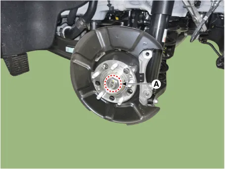
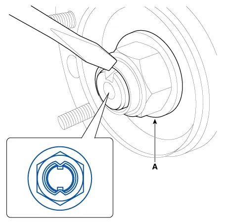
Loosen the driveshaft caulking nut (A).
|

| 6. |
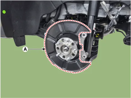
Loosen the bolts and then removing the rear hub assembly and duct cover
(A).
|
| 7. |
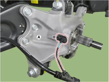
Loosen the bolt and then removing the wheel speed sensor (A).
|
| 8. |
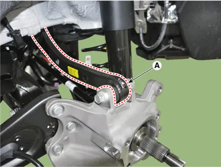
Loosen the nut and bolt and then removing the rear upper arm (A) from
the axle.
|
| 9. |
Loosen the bolt and nut and then separate the rear assist arm (A) from
the rear axle.
|
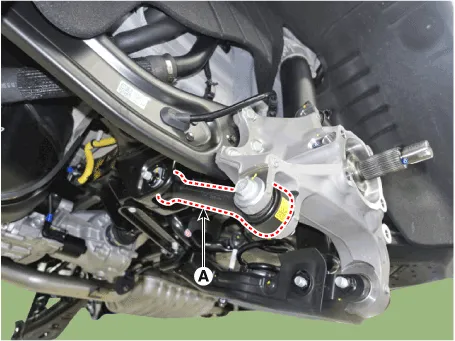
| 10. |
Loosen the mounting nut (A) and then separate the trailing arm from
the rear carrier assembly.
|
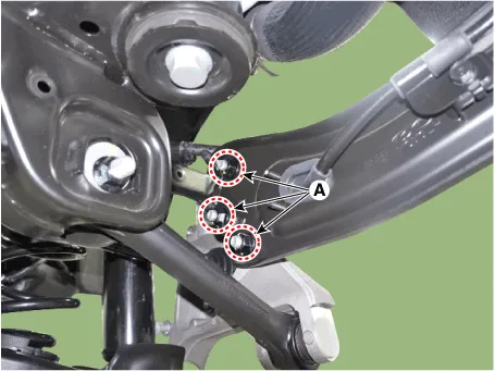
| 11. |
Remove the rear axle carrier (A) after loosening the bolt and nut.
|
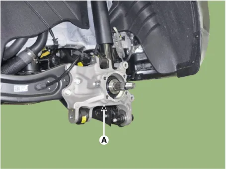
| Inspection |
| 1. |
Check the hub for cracks and the splines for wear.
|
| 2. |
Check the rear axle carrier for cracks.
|
| Installation |
| 1. |
Install in the reverse order of removal.
|
| 2. |
Check the alignment.
(Refer to Suspension System - "Alingment")
|
Other information:
Hyundai Palisade (LX2) 2020-2026 Service Manual: Specifications
Specification Air Conditioner Item Specification Compressor Type 7VSX18 (External Variable Displacement Swash Plate) Oil type & Capacity PAG 180 ± 10cc (6.
Hyundai Palisade (LX2) 2020-2026 Service Manual: Components and components location
Categories
- Manuals Home
- Hyundai Palisade Owners Manual
- Hyundai Palisade Service Manual
- Engine Electrical System
- Resetting the Driver's Seat Memory System
- Automatic Transaxle Fluid (ATF)
- New on site
- Most important about car

Copyright © 2026 www.hpalisadelx.com - 0.0257