Hyundai Palisade (LX2): Power Door Mirrors / Power Door Mirror Actuator
Hyundai Palisade (LX2) 2020-2026 Service Manual / Body Electrical System / Power Door Mirrors / Power Door Mirror Actuator
Repair procedures
| Removal |
| 1. |
Disconnect (-) battery terminal.
|
| 2. |
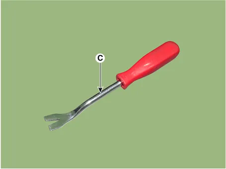
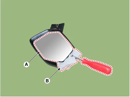
Using a fastener remover (C), remove the mirror (A) as illustration
below.
|

| 3. |
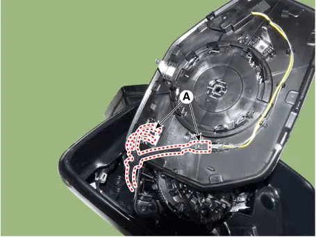
Disconnect heat wire connectors (A) and then remove the mirror.
|
| 4. |
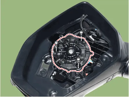
Remove the mirror actuator mounting screw.
|
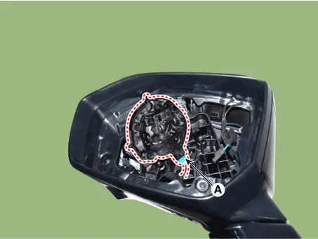
| 5. |
Disconnect the connector (A) and then remove the mirror actuator.
|
| Installation |
| 1. |
Connect the actuator connector and then install the mirror actuator.
|
| 2. |
Connect mirror heat wire connector and then install the mirror.
|
| 3. |
Connect (-) battery terminal then check if mirror works normally.
|
Schematic diagrams Circuit Diagram Repair procedures Removal 1. Disconnect the negative (-) battery terminal.
Components and components location Components 1. Blind spot radar warning indicator 2. Side repeater lamp 3. Puddle lamp 4.
Other information:
Hyundai Palisade (LX2) 2020-2026 Service Manual: Description and operation
Hyundai Palisade (LX2) 2020-2026 Service Manual: Description and operation
Description and Operation Blcok Diagram • This system monitors the driving situations through the radar and the camera. Thus, for a situation out of the sensing range, the system may not normally operate.
Categories
- Manuals Home
- Hyundai Palisade Owners Manual
- Hyundai Palisade Service Manual
- Automatic Transaxle Fluid (ATF)
- Lift and Support Points
- How to reset the power liftgate
- New on site
- Most important about car

Copyright © 2026 www.hpalisadelx.com - 0.0133