Hyundai Palisade (LX2): Power Door Mirrors / Power Door Mirror Switch
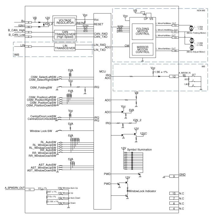
Schematic diagrams
| Circuit Diagram |
Repair procedures
| Removal |
| 1. |
Disconnect the negative (-) battery terminal.
|
| 2. |
Remove the front left door trim.
(Refer to Body - "Front Door Trim")
|
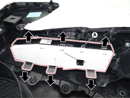
| 3. |
Disengage the mounting clip and then remove the door rock switch assembly
(A).
|
| Installation |
| 1. |
Install the power mirror switch.
|
| 2. |
Install the front door trim after connecting the connector.
|
| 3. |
Connect the negative (-) battery terminal.
|
| Inspection |
| 1. |
In the body electrical system, failure can be quickly diagnosed by using
the vehicle diagnostic system (Diagnostic tool).
The diagnostic system (Diagnostic tool) provides the following information.
|
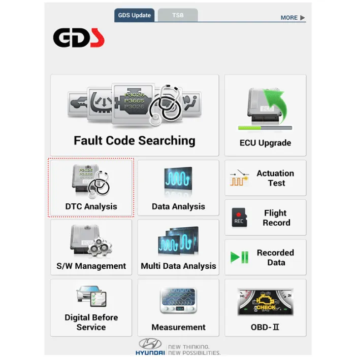
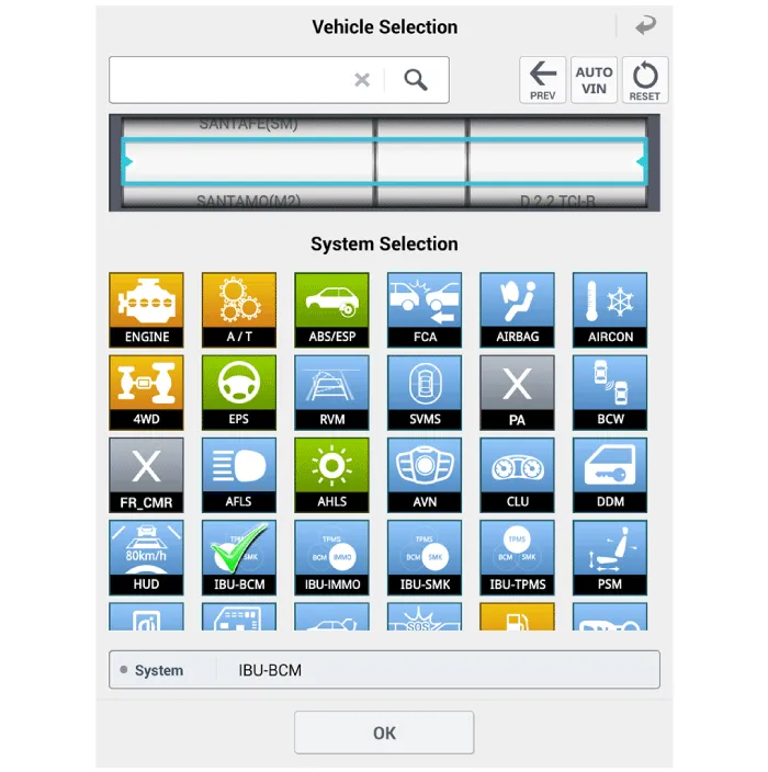
| 2. |
If diagnose the vehicle by Diagnostic tool, select "DTC Analysis" and
"Vehicle".
|
| 3. |
If check current status, select the "Data Analysis" and "Car model".
|
| 4. |
Select the 'IBU_BCM' to search the current state of the input/output
data.
|

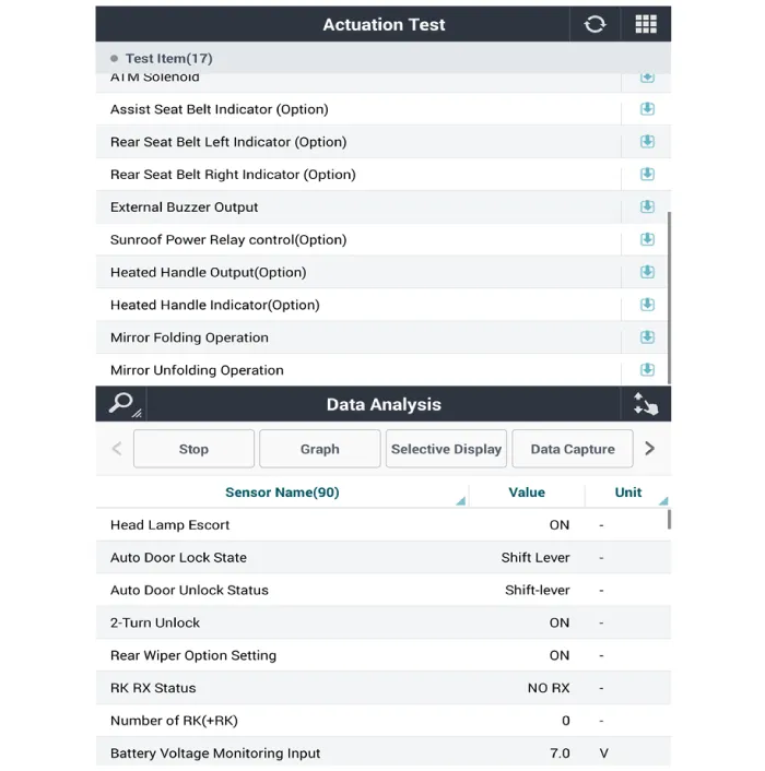
| 5. |
To forcibly actuate the input value of the module to be checked, select
option 'Actuation Test'.
|
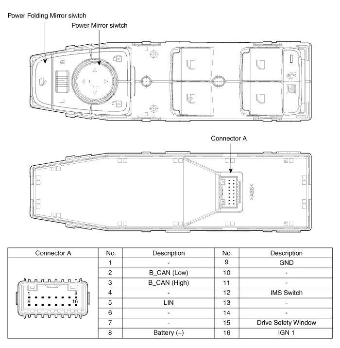
Component Location 1. Power door mirror 2. Power door mirror switch 3. Power folding mirror switch
Repair procedures Removal 1. Disconnect (-) battery terminal. 2. Using a fastener remover (C), remove the mirror (A) as illustration below.
Other information:
Hyundai Palisade (LX2) 2020-2026 Service Manual: Auto Defogging Sensor
Description and operation Description The auto defogging sensor is installed on the front window glass. The sensor judges and sends signal if moisture occurs to blow out wind for defogging. The air conditioner control module receives signal from the sensor and restrains moisture and eliminate defog by controlling the intak
Hyundai Palisade (LX2) 2020-2026 Service Manual: Description and operation
Description Rear view camera will activate when the backup light is ON with the ignition switch ON and the shift lever in the R position. This system is a supplemental system that shows behind the vehicle through the AV monitor or the ECM (Reverse Display Room Mirror) mirror while backing-up.
Categories
- Manuals Home
- Hyundai Palisade Owners Manual
- Hyundai Palisade Service Manual
- Emergency liftgate safety release
- Automatic Transaxle Fluid (ATF)
- Convenient Features of Your Vehicle
- New on site
- Most important about car
