Hyundai Palisade (LX2): Lubrication System / Oil Pan
Components and components location
| Components |
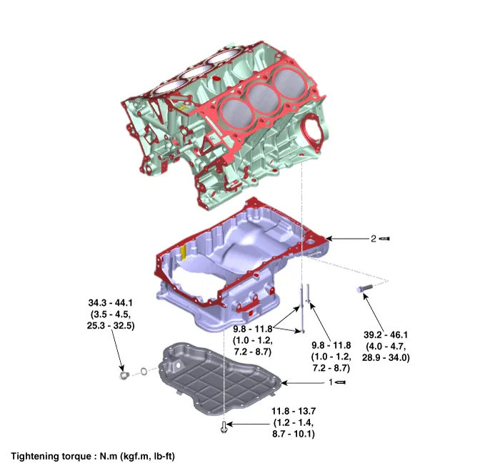
| 1. Lower oil pan |
2. Upper oil pan |
Repair procedures
| Removal |
|

| 1. |
Remove the engine room under cover.
(Refer to Engine and Transaxle Assembly - "Engine Room Under Cover")
|
| 2. |
Drain the engine oil.
(Refer to Lubrication System - "Engine Oil")
|
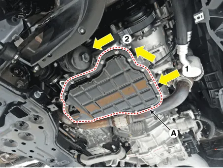
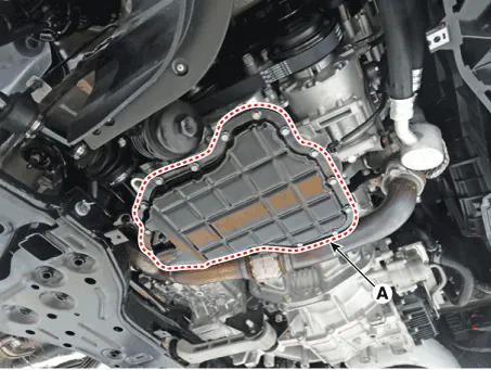
| 3. |
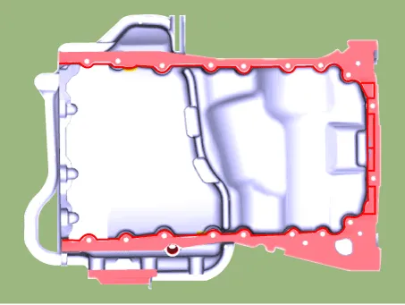
Remove the lower oil pan (A).
Insert the blade of SST (09215-3C000) between the upper oil pan and
lower oil pan. Cut off applied sealer and remove the lower oil pan.
|


| 1. |
Remove the lower oil pan.
|
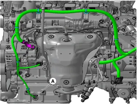
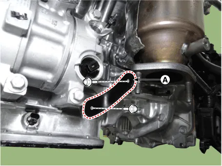
| 2. |
Disconnect the oil pump solenoid valve extension wiring connector (A).
|
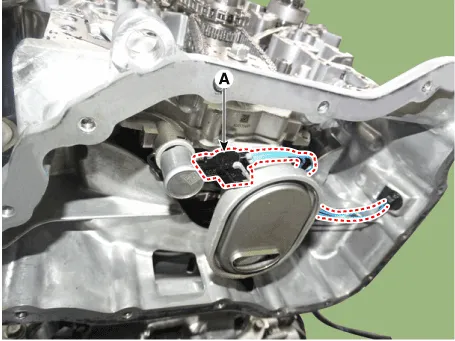
| 3. |
Disconnect the oil pump solenoid valve connector (A).
|
| 4. |
Remove the front muffler.
(Refer to Intake and Exhaust System - "Muffler")
|
| 5. |
Separate the compressor.
(Refer to Heating, Ventilation Air conditioning - "Compressor")
|
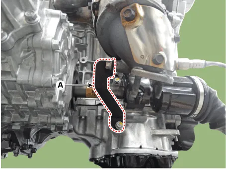
| 6. |
Remove the LH exhaust manifold stay (A).
|
| 7. |
Remove the RH exhaust manifold stay (A).
|
| 8. |
Remove the surge tank.
(Refer to Intake and Exhaust System - "Surge Tank")
|
| 9. |
Remove the LH and RH cylinder head cover.
(Refer to Cylinder Head Assembly - "Cylinder Head Cover")
|
| 10. |
Install the engine support fixture.
(Refer to Automatic Transaxle System - "Special Service Tools")
|
| 11. |
Remove the timing chain cover.
(Refer to Timing System - "Timing Chain Cover")
|
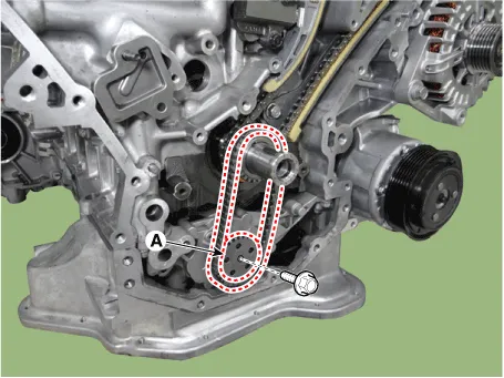
| 12. |
Remove the oil pump chain tensioner (A).
|
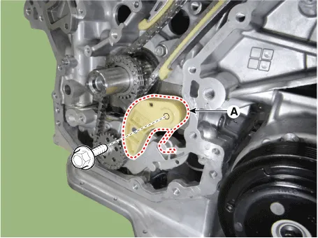
| 13. |
Remove the oil pump chain sprocket (A).
|
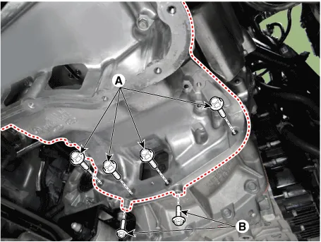
| 14. |
Remove the transaxle mounting bolt (A) and upper oil pan mounting bolt
(B).
|
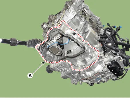
| 15. |
Insert the blade of SST (09215-3C000) between the upper oil pan and
cylinder block. Cut off applied sealer and remove the upper oil pan
(A).
|
| Installation |
| 1. |
Install the lower oil pan (A).
|

| 2. |
After assembly, wait for at least 30 minutes before filling the engine
with oil.
|
| 3. |
Install the remaining parts in the reverse order of removal.
|
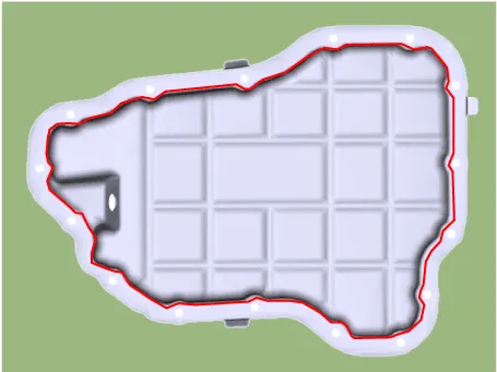
| 1. |
Install the upper oil pan.
|

| 2. |
Install the remaining parts in the reverse order of removal.
|
Components and components location Components 1. Oil fliter body 2. Gasket Repair procedures Removal • Be careful not to damage the parts located under the vehicle (floor under cover, fuel filter, fuel tank and canister) when raising the vehicle using the lift.
Repair procedures Removal and Installation • Be careful not to damage the parts located under the vehicle (floor under cover, fuel filter, fuel tank and canister) when raising the vehicle using the lift.
Other information:
Hyundai Palisade (LX2) 2020-2026 Service Manual: Components and positions
Hyundai Palisade (LX2) 2020-2026 Service Manual: Description and operating principle
Description and Operation Wireless Power Charger System During ACC or IG ON, battery voltage is supplied to the wireless power charger system to transmit an output of 5 W to mobile phone. Mobile phones certified with the wireless charging standard WPC (Qi 1.
Categories
- Manuals Home
- Hyundai Palisade Owners Manual
- Hyundai Palisade Service Manual
- Electronic Child Safety Lock System
- Automatic Transaxle Fluid (ATF)
- Lift and Support Points
- New on site
- Most important about car
