Hyundai Palisade (LX2): Engine Control System / Heated Oxygen Sensor (HO2S)
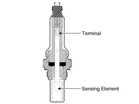
Description and operation
| Description |
Specifications
| Specification |
|
Item |
Specification |
|
Heater Resistance (‚Ą¶) |
2.4 - 4.0 [20¬įC (68¬įF)] |
|
Operation Voltage (V) |
12 |
|
pin |
6 |
|
Item |
Specification |
|
Heater Resistance (‚Ą¶) |
3.3 - 4.1 [20¬įC (68¬įF)] |
|
pin |
4 |
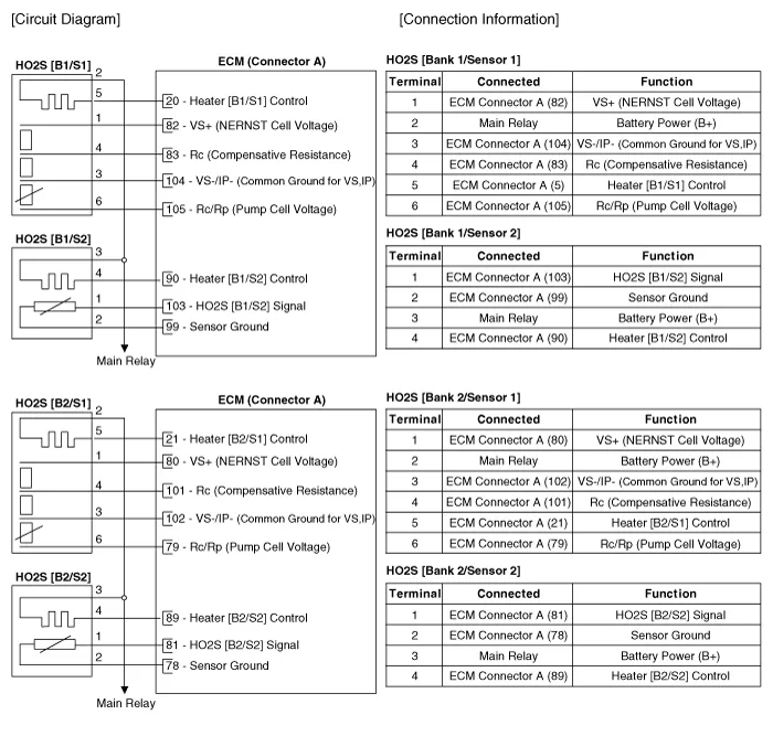
Schematic diagrams
| Circuit Diagram |
Repair procedures
| Inspection |
| 1. |
Switch "OFF" the ignition.
|
| 2. |
Disconnect the HO2S connector.
|
| 3. |
Measure resistance between the HO2S terminals 2 and 5 [Bank 1 / Sensor
1, Bank 2 / Sensor 1]
Measure resistance between the HO2S terminals 1 and 2 [Bank 1 / Sensor
2, Bank 2 / Sensor 2]
|
| 4. |
Check that the resistance is within the specification.
|
| Removal |
| 1. |
Switch "OFF" the ignition and disconnect the negative (-) battery terminal.
|
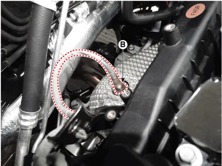
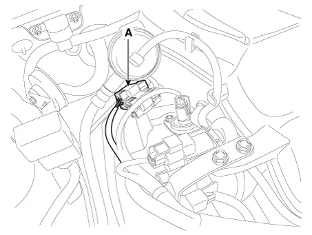
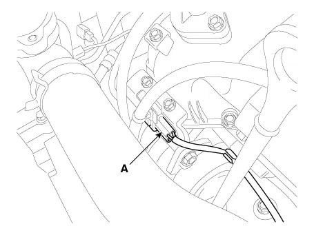
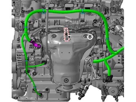
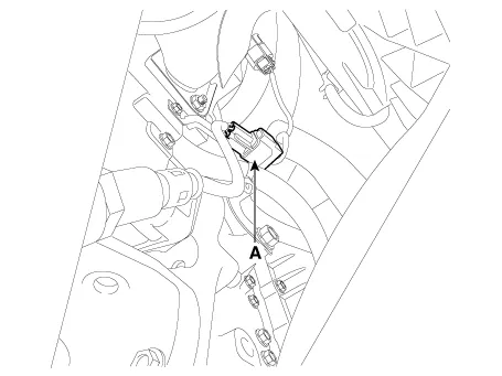
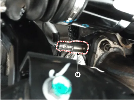
| 2. |
Remove the oxygen sensor (B) after disconnect the Connector (A).
[Bank 1 / Sensor 1]
[Bank 1 / Sensor 2]
[Bank 2 / Sensor 1]
[Bank 2 / Sensor 2]
|


| Installation |
|

| 1. |
Install in the reverse order of removal.
|
Description and operation Description Knocking is a phenomenon characterized by undesirable vibration and noise that can cause engine damage.
Description and operation Description Installed on the delivery pipe, the Rail Pressure Sensor (RPS) measures the instantaneous fuel pressure in the delivery pipe.
Other information:
Hyundai Palisade (LX2) 2020-2026 Service Manual: Climate Control Air Filter
Description and operation Description The climate control air filter is located in the blower unit. It eliminates foreign materials and odor. The particle filter performs a role as an odor filter as well as a conventional dust filter to ensure comfortable interior environment.
Hyundai Palisade (LX2) 2020-2026 Service Manual: Troubleshooting
Trouble Symptom Charts Trouble Symptom 1 Trouble Symptom 2 Trouble symptom Probable cause Remedy The set vehicle speed varies greatly upward or downward "Surging" (repeated alternating acceleration and deceleration) occurs after set
Categories
- Manuals Home
- Hyundai Palisade Owners Manual
- Hyundai Palisade Service Manual
- Power Outlet
- Body (Interior and Exterior)
- Rain Sensor
- New on site
- Most important about car
