Hyundai Palisade (LX2): Engine Control System / Rail Pressure Sensor (RPS)
Description and operation
| Description |

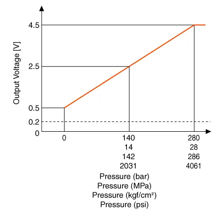
Specifications
| Specification |
|
Pressure |
Output Voltage (V) [Vref=5V] |
|
|
bar |
[MPa (kgf/cm², psi)] |
|
|
0 |
0 (0, 0) |
0.5 |
|
140 |
14 (142, 2031) |
2.5 |
|
280 |
28 (286, 4061) |
4.5 |
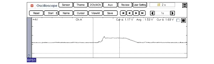
Troubleshooting
| Signal Waveform |
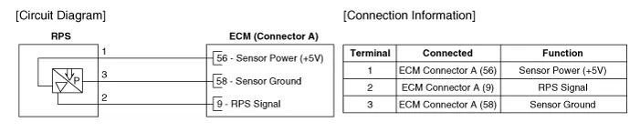
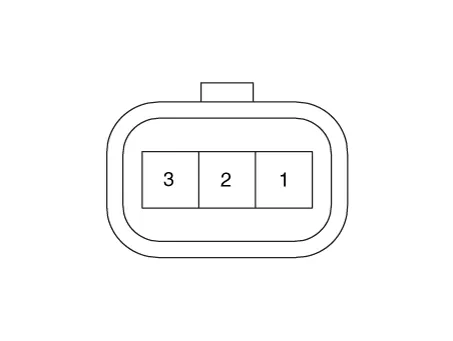
Schematic diagrams
| Circuit Diagram |
Repair procedures
| Inspection |
| 1. |
Connect the diagnostic tool on the Data Link Connector (DLC).
|
| 2. |
Measure the output voltage of the RPS at idle and various engine speed.
|
||||||||||||||
| Removal |
| 1. |
Release the residual pressure in fuel line.
(Refer to Fuel Delivery System - "Release Residual Pressure in Fuel
Line")
|
| 2. |
Switch "OFF" the ignition and disconnect the negative (-) battery terminal.
|
| 3. |
Remove the intake manifold.
(Refer to Engine Mechanical System - "Intake Manifold")
|
| 4. |
Disconnect the rail pressure sensor connector (A), and then remove the
sensor (B) from the delivery pipe.
|

| Installation |
|

| 1. |
Install in the reverse order of removal.
|
Description and operation Description Heated Oxygen Sensor (HO2S), consisting of zirconium and alumina, is installed on both upstream and downstream of the Manifold Catalytic Converter (MCC) to detect the air/fuel ratio and send it to the ECM.
Description and operation Description Continuous Variable Valve Timing (CVVT) system advances or retards the valve timing of the intake and exhaust valve in accordance with the ECM control signal which is calculated by the engine speed and load.
Other information:
Hyundai Palisade (LX2) 2020-2026 Service Manual: Parking/View Switch
Repair procedures Removal 1. Disconnect the negative (-) battery terminal. 2. Remove the floor console upper cover. (Refer to Body - "Floor Console Assembly") 3.
Hyundai Palisade (LX2) 2020-2026 Service Manual: Description and operation
Description The cruise control system is engaged by the cruise "ON/OFF" main switch located on right of steering wheel column. The system has the capability to cruise, coast, accelerate and resume speed. It also has a safety interrupt, engaged upon depressing brake or shifting select lever.
Categories
- Manuals Home
- Hyundai Palisade Owners Manual
- Hyundai Palisade Service Manual
- Resetting the Driver's Seat Memory System
- Electronic Child Safety Lock System
- General Tightening Torque Table
- New on site
- Most important about car
