Hyundai Palisade (LX2): Fuel Delivery System / Fuel Pump
Repair procedures
| Inspection |
| 1. |
Turn ignition switch OFF and disconnect the negative (-)battery cable.
|
| 2. |
Remove the fuel pump assembly.
|
| 3. |
Check motor operation by fuel pump connector (A) connecting power (No.1)
and ground (No.6).
|
| 4. |
Also check that the resistance changes smoothly when the float is moved
from "E" to "F".
|
| Removal |
| 1. |
Release the residual pressure in fuel line.
(Refer to Fuel Delivery System - "Release Residual Pressure in Fuel
Line")
|
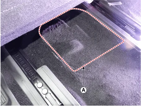
| 2. |
Remove the floor carpet service cover (A).
|
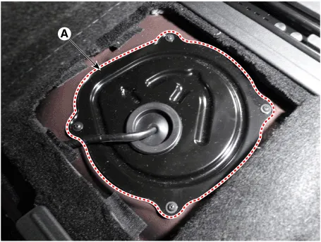
| 3. |
Remove the fuel pump service cover (A) after loosening the mounting
screws.
|
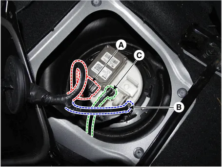
| 4. |
Disconnect the fuel pump control module connector (A) and fuel pressure
sensor connector (B).
|
| 5. |
Disconnect fuel feed tube quick-connector (C).
|
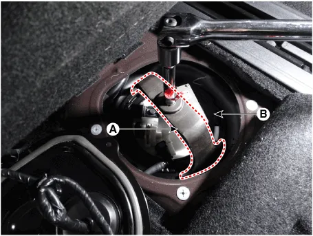
| 6. |
Remove the locking ring (A) by using the special service tool [No.:
09310-B8100].
|

| 7. |
Remove the fuel pump from the fuel tank.
|

| Installation |
| 1. |
Install in the reverse order of removal.
|
Repair procedures • Be careful not to damage the parts located under the vehicle (floor under cover, fuel filter, fuel tank and canister) when raising the vehicle using the lift.
Description and operation Description The fuel pump control module (FPCM) is installed on the right side of the fuel tank and controls the DC motor mounted inside the low pressure fuel pump.
Other information:
Hyundai Palisade (LX2) 2020-2026 Service Manual: Blower Unit
Components and components location Components Location 1. Blower unit assembly Components 1. Intake seal 2. Intake upper case 3. Intake actuator 4. Intake door 5.
Hyundai Palisade (LX2) 2020-2026 Service Manual: Description and operation
Description Surround View Monitor (SVM) is the system that allows video monitoring of 360 degrees around the vehicle. The system includes 4 ultra optical camera mounted around the vehicle (front, both sides, rear). The video from these cameras are applied with distortion compensation, time point conversion, and video me
Categories
- Manuals Home
- Hyundai Palisade Owners Manual
- Hyundai Palisade Service Manual
- Resetting the Driver's Seat Memory System
- Components and components location
- Body (Interior and Exterior)
- New on site
- Most important about car
