Hyundai Palisade (LX2): Hydraulic System / Description and operation
Hyundai Palisade (LX2) 2020-2026 Service Manual / Automatic Transaxle System (A8LF1) / Hydraulic System / Description and operation
| Description |
| • |
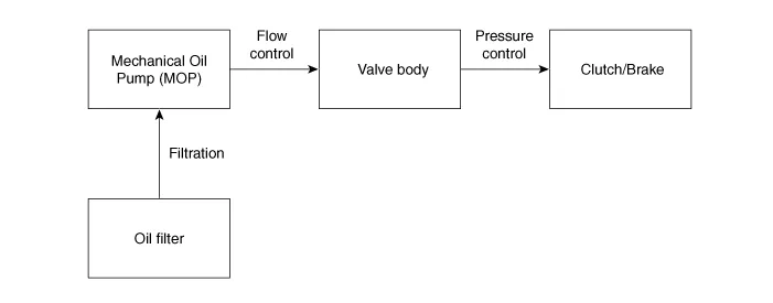
The hydraulic system consists of a valve body, an oil filter and an
oil pump.
|
| • |
The oil pump is powered by the engine. ATF passes through the oil filter
and gets distributed along the oil channels.
|
| • |
The oil becomes highly pressurized as it exits the oil pump and passes
through the line pressure valve before being fed to the clutch & brake
control valve, clutch, and brakes.
|
| • |
TCM controls the hydraulic pressure using solenoid valves and controls
clutch and brake operations.
Flow of the hydraulic system
|
Components Location 1. Valve body assembly 2. Solenoid valve
Other information:
Hyundai Palisade (LX2) 2020-2026 Service Manual: Wireless Charging Lamp
Components and positions Components Repair procedures Removal Handling wireless charging system parts by wet hands may cause electric shock.
Hyundai Palisade (LX2) 2020-2026 Service Manual: Rear Corner Safety ON/OFF Switch
Components and components location Circuit Diagram Repair procedures Inspection 1. Disconnect the negative (-) battery terminal. 2. Remove the crash pad lower panel. (Refer to Body - "Crashpad Lower Panel") 3.
Categories
- Manuals Home
- Hyundai Palisade Owners Manual
- Hyundai Palisade Service Manual
- Engine Mechanical System
- Body Electrical System
- Emergency liftgate safety release
- New on site
- Most important about car

Copyright © 2026 www.hpalisadelx.com - 0.016