Hyundai Palisade (LX2): Automatic Transaxle System / Automatic Transaxle
Hyundai Palisade (LX2) 2020-2026 Service Manual / Automatic Transaxle System (A8LF1) / Automatic Transaxle System / Automatic Transaxle
Repair procedures
| Removal |
|

| 1. |
Turn ignition switch OFF and disconnect the negative (-) battery cable.
|
| 2. |
Remove the air duct and the air cleaner assembly.
(Refer to Engine Mechanical System - "Air Cleaner")
|
| 3. |
Remove the battery and battery tray.
(Refer to Engine Electrical System - "Battery")
|
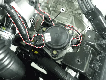
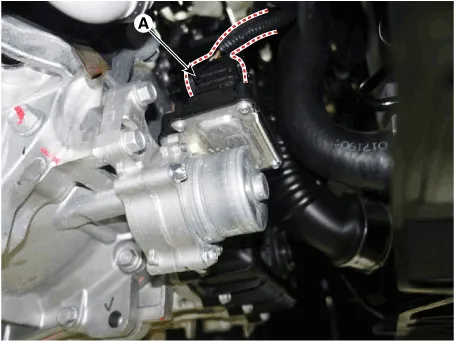
| 4. |
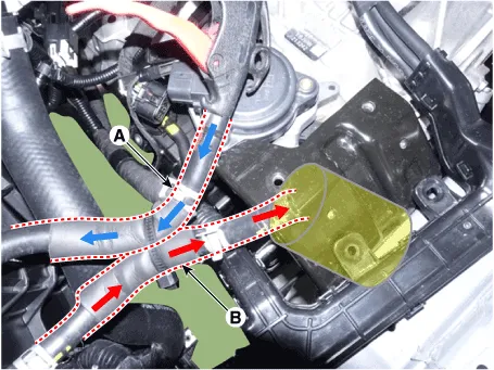
Disconnect the main connector (A), electronic shift actuator connector
(B) and position sensor connector (C).
|
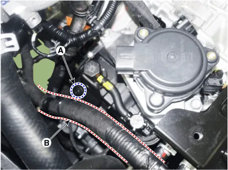
| 5. |
Remove the bolt (A) and then separate the wiring (B).
|
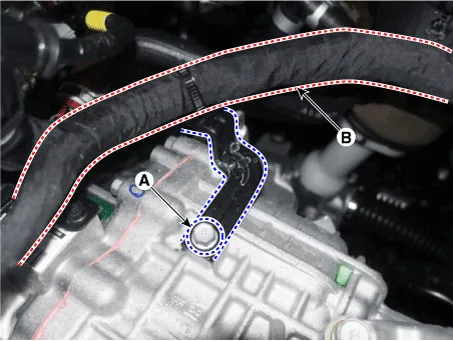
| 6. |
Loosen the bolt (A) and then separate the wiring (B).
|
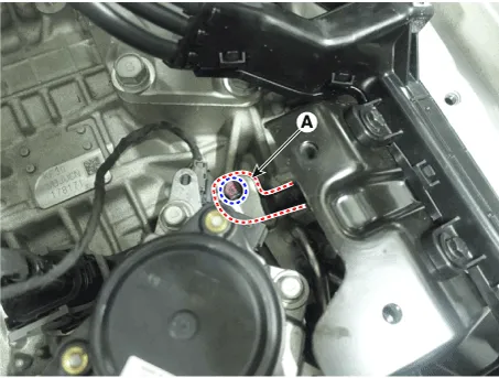
| 7. |
Remove the ground line (A).
|
| 8. |
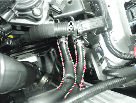
Separate the ATF cooler hose (A).
|
| 9. |
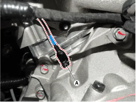
Remove the CKP sensor (A) after loosening the bolt.
|
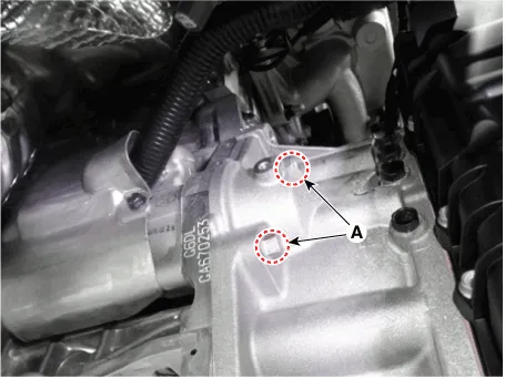
| 10. |
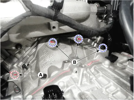
Remove the transaxle upper mounting bolts (A, B).
|
| 11. |
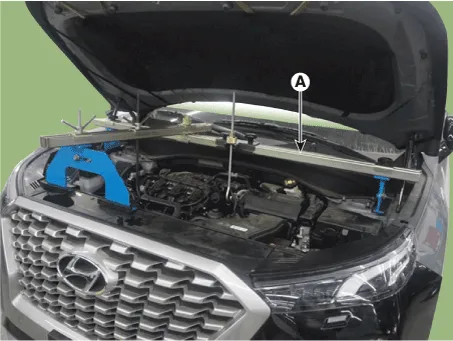
Assemble the engine support fixture use a (Beam SST No..: 09200 - 3N000,
Supporter SST No..: 09200-2S000, Adaptor SST No..: 09200-2W000).
|
| 12. |
Using the engine support fixture, hold the engine and transaxle assembly
safely.
|

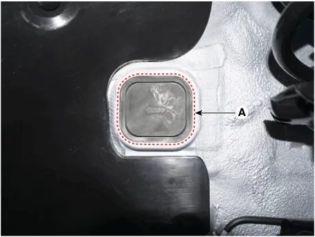
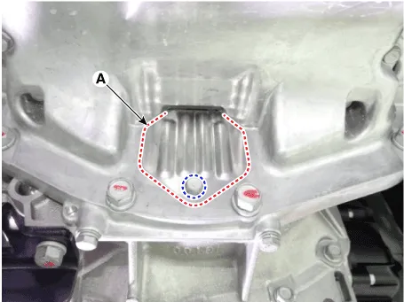
| 13. |
Remove the cover (A).
|
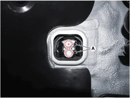
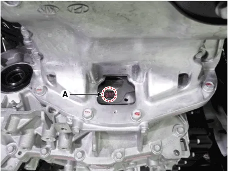
| 14. |
Remove the transaxle mounting bracket bolts (A).
|
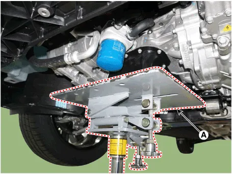
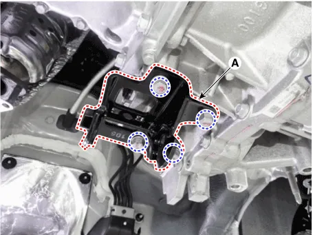
| 15. |
Loosen the transaxle support bracket mounting bolts and then removing
the transaxle support bracket (A).
|
| 16. |
Remove the under cover.
(Refer to Engine Mechanical System - "Engine Room Under Cover")
|
| 17. |
Remove the sub frame.
(Refer to Suspension System - "Sub Frame")
|
| 18. |
Remove the driveshaft assembly.
(Refer to Driveshaft and Axle - "Front Driveshaft")
|
| 19. |
In case of 4WD vehicle, remove the transfer assembly.
(Refer to 4 Wheel Drive System-"Transfer Assembly")
|
| 20. |
Disconnect the EOP(Electronic Oil Pump) connector (A).
|
| 21. |
Remove the dust cover (A).
|
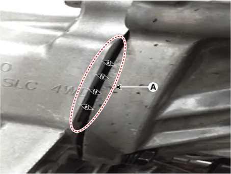
| 22. |
Remove the torque converter mounting bolts (A) by rotating the crankshaft.
|
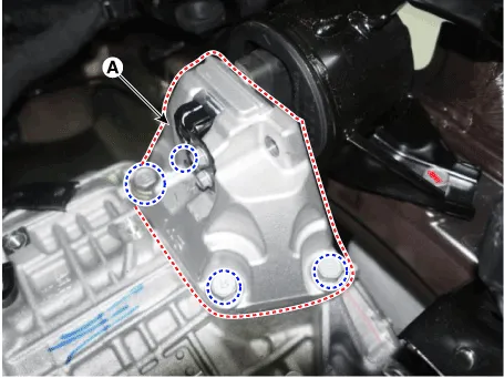
| 23. |
Remove the roll rod support bracket (A).
|
| 24. |
Support the transaxle safely with a jack.
|
| 25. |
Remove the starter mounting bolts (A).
|
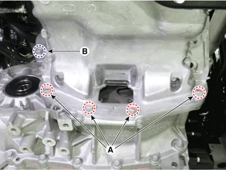
| 26. |
Loosen the transaxle lower mounting bolts (A, B).
|
| 27. |
After separating the transaxle from the engine, remove the transaxle
by lowering the jack slowly.
|

| Installation |
| 1. |
To install, reverse the removal procedure.
|

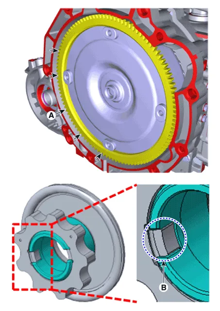

| 2. |
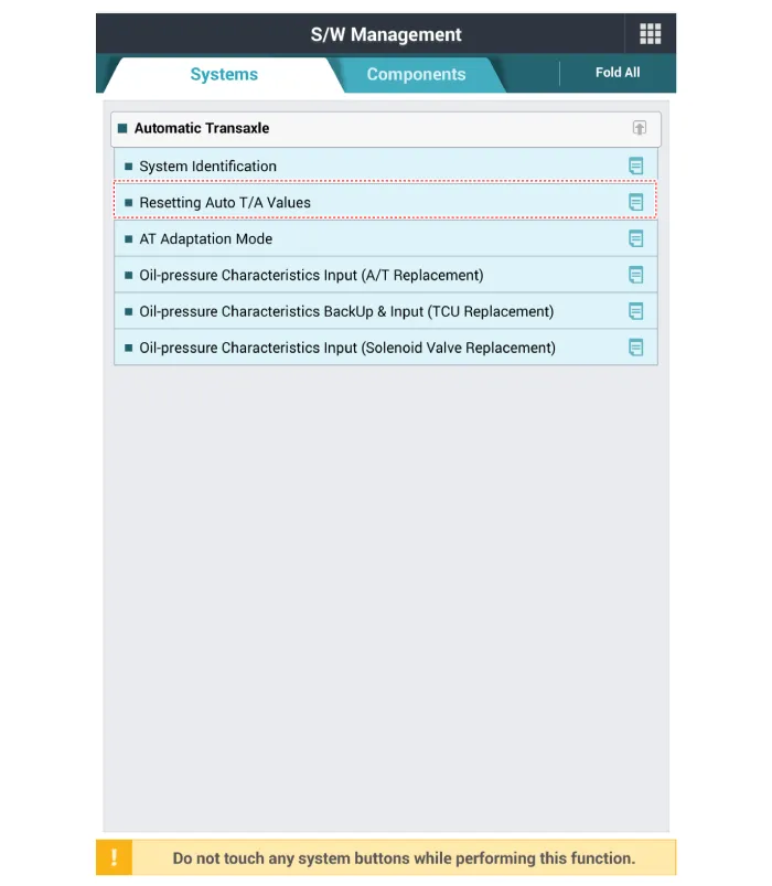
In case of the reinstallation.
|


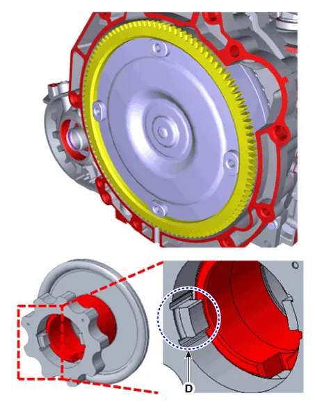
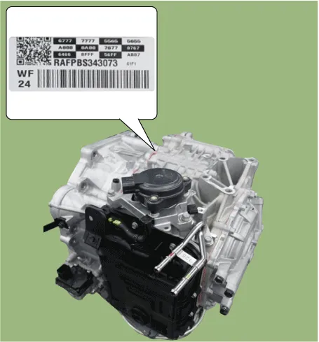
| 3. |
In case of the replacing with a new automatic transaxle.
|


Components and components location Components Location 1. ATF Injection plug (Eyebolt) 2. ATF injection plug gasket 3.
Other information:
Hyundai Palisade (LX2) 2020-2026 Service Manual: Wireless Power Charging Unit
Components and positions Components Circuit diagram Circuit Diagram Repair procedures Removal Handling wireless charging system parts by wet hands may cause electric shock.
Hyundai Palisade (LX2) 2020-2026 Service Manual: Front View Camera Unit
Schematic diagrams Circuit Diagram Repair procedures Removal 1. Disconnect the negative (-) battery terminal. 2. Remove the inside rear view mirror cover (A) and rain sensor cover (B).
Categories
- Manuals Home
- Hyundai Palisade Owners Manual
- Hyundai Palisade Service Manual
- Automatic Transaxle System (A8LF1)
- Convenient Features of Your Vehicle
- Electronic Child Safety Lock System
- New on site
- Most important about car

Copyright © 2026 www.hpalisadelx.com - 0.0191